- Country
- Great Britain (UK)
- Manufacturer / Brand
- Standard Telephones and Cables Ltd. (STC); London, Foots Cray
- Year
- 1935–1942
- Category
- Military Receiver
- Radiomuseum.org ID
- 110460
-
- Brand: Micromesh tubes
Click on the schematic thumbnail to request the schematic as a free document.
- Number of Tubes
- 6
- Main principle
- TRF with regeneration; 3 AF stage(s)
- Tuned circuits
- 2 AM circuit(s)
- Wave bands
- Wave Bands given in the notes.
- Power type and voltage
- Storage and/or dry batteries / 2 & 120 Volt
- Loudspeaker
- - For headphones or amp.
- Material
- Wooden case
- from Radiomuseum.org
- Model: R1082 - Standard Telephones and Cables
- Shape
- Tablemodel, with any shape - general.
- Dimensions (WHD)
- 10.5 x 11.5 x 9 inch / 267 x 292 x 229 mm
- Notes
- The receiver covered 111 kHz to 15 MHz in 14 bands with exchangable coil pairs for aerial and anode circuits (28 coils). It could also be used for direction finding DF with an add on unit.
- Net weight (2.2 lb = 1 kg)
- 7 kg / 15 lb 6.7 oz (15.419 lb)
- Mentioned in
- Air Publication 1186 Dec. 1938 and Radio Bygones.
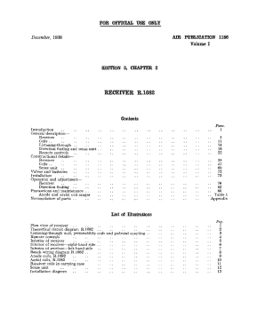
| Receiver R1082, Sect 3, Chap 2 Dec 1938 | 3859 KB |
- Documents regarding this model
- Other Models
-
Here you find 39 models, 34 with images and 11 with schematics for wireless sets etc. In French: TSF for Télégraphie sans fil.
All listed radios etc. from Standard Telephones and Cables Ltd. (STC); London, Foots Cray
Collections
The model is part of the collections of the following members.
Museums
The model can be seen in the following museums.
Forum contributions about this model: Standard Telephones: R1082
Threads: 1 | Posts: 4
STC R1082
The receiver R1082 was designed in the middle of the 1930s by STC (Standard Telephone & Cables), and was used together with the companion transmitter T1083 in early versions of light and heavy bombers like the Fairey Swordfish and Battle, Handley Page Hampden, Armstrong Whitworth Whitley, Vickers Wellington and the first fourengined bomber, the Short Stirling. The R1082/T1083 were eventually replaced by the R1155/T1154 in the beginning of the 1940s.
At the outbreak of the war in 1939, the R1082/T1083 together with the TR9 were the dominating radio systems in the Royal Air Force, but they were already obsolete at that time. They were also used in sea rescue vessels and after being phased out of the aircraft they were used for ground communication.
According to a reader of Radio Bygones working as a post-war radio mechanic the R1082/T1083 were still used in Ansons and Oxfords as late as in the beginning of the 1960s!R1082/T1083 were also used by the Australian and Canadian air forces. In Australia a slightly redesigned and not very reliable copy was made, designated the AR14/AT10.
Receiver Data
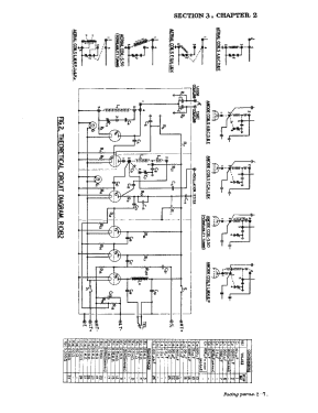
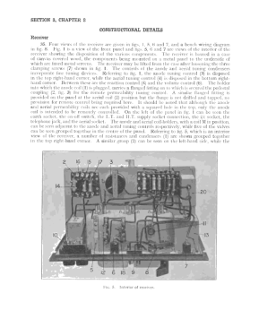
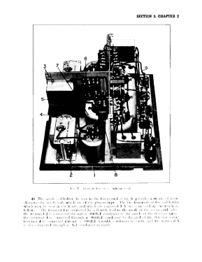
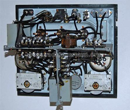
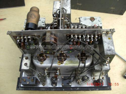
The R1082 is a simple straight regenerative receiver with 5 valves plus a protective diode across the antenna input. The first stage is an RF amplifier pentode, followed by a triode detector with positive feedback, two AF amplifier triodes and another triode as AF output stage for headphones. The equipment also provides intercommunication for the crew.
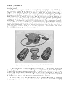
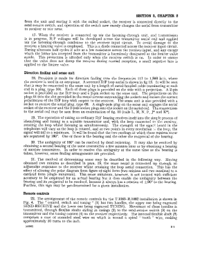
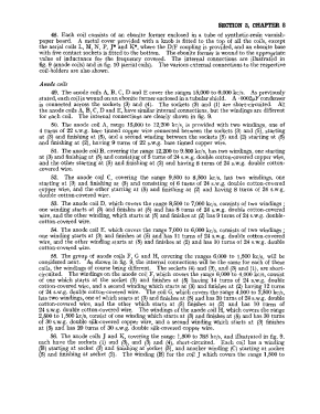
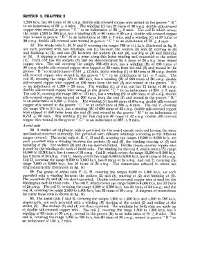
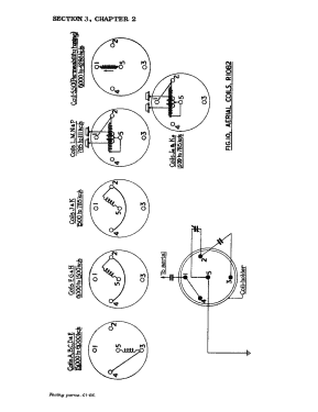
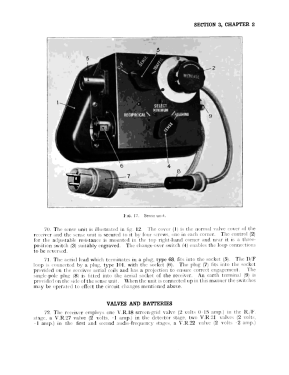
The receiver covers 111 kHz to 15 MHz in 14 bands with interchangeable coils, and it can be used for CW and R/T. The coils come in pairs, aerial (input) coil and anode coil for the RF stage. For full frequency coverage there are 28 coils in a special carrying case. The lower frequency bands can be used for D/F (direction finding), using a D/F add-on and a loop aerial.
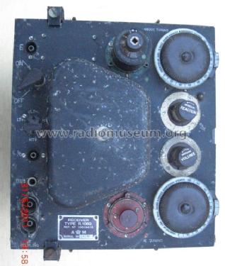
The receiver is a two-hand device with one hand on the tuning knobs and the other on the feedback knob, and it needs a skilled operator to do a good job. The operators made their own calibration charts for each individual receiver they used. The positive feedback is inductively coupled from the detector output to the RF anode coil. The degree of feedback is regulated with a potentiometer changing the RF gain. Close to the self oscillation point the positive feedback gives a very high gain. The receiver sensitivity is 25 uV for 5 mV output into 20 kohm.
In the aircraft the receiver was fed by a 2 V 20 Ah lead acid ackumulator for the LT, current 1.15 A, and an anode battery giving 120 V HT, current around 13 mA. The receiver measures 27 cm x 29 cm x 23 cm (w x h x d), and the weight is a little under 7 kilos with coils.
My Receiver
The R1082 receiver has the model number 10D/8415 and my receiver has the serial number 15589. I recently bought it on eBay. According to the seller it was bought as military surplus after the war by a science teacher (probably with some connection to the RAF in WWII), and he used it as a demonstrator at his school when teaching radio. It was then taken over by one of the pupils in 1965, and it was last used around 1975.
The receiver is in its original condition, no changes at all have been made, and no restoration will be needed except a check of the components and a final check. Coils D, E, F, K and L were delivered, (together with some spare coils for these bands), covering the frequency bands 470 - 785 and 785 - 1200 kHz, of which the lower one has coils for D/F, and 4000 - 8500 kHz.
More details and pictures can be found on my home page http://goto.glocalnet.net/bosradio .
Attachments
- R1082 front (88 KB)
- R1082 chassis (86 KB)
- R1082 valves (96 KB)
Bo Samuelsson, 23.Dec.06

