- Country
- Australia
- Manufacturer / Brand
- Standard Telephones and Cables Pty, Ltd (STC), Sydney
- Year
- 1936
- Category
- Broadcast Receiver - or past WW2 Tuner
- Radiomuseum.org ID
- 335138
Click on the schematic thumbnail to request the schematic as a free document.
- Number of Tubes
- 5
- Main principle
- Superheterodyne (common); ZF/IF 450 kHz; 2 AF stage(s)
- Tuned circuits
- 6 AM circuit(s)
- Wave bands
- Broadcast only (MW).
- Power type and voltage
- Alternating Current supply (AC) / 200; 250 Volt
- Loudspeaker
- Electro Magnetic Dynamic LS (moving-coil with field excitation coil) / Ø 8 inch = 20.3 cm
- Material
- Wooden case
- from Radiomuseum.org
- Model: 511A Ch= 51A - Standard Telephones and Cables
- Shape
- Console with any shape - in general
- Notes
-
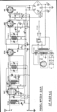
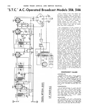
STC Models 511A & 514A are 5-valve Console type receivers designed for broadcast coverage and operation from 200-250 volts AC mains.
Apart from the cabinet style, these two receivers are identical & employ a chassis known as type “51A”. This chassis is fitted with two controls, tuning & volume & uses an 8-inch, 2,500Ω field, loudspeaker.
The arrangement of this receiver is fairly straightforward, but there are one or two points that should be carefully noted.
The first of these is that the aerial coil is connected directly to the low-potential end of the 6A7 grid coil; this means that the aerial itself is “floating” at AVC potential & consequentially, any leakage from aerial to earth will reduce the AVC & may in a severe case actually stop the AVC system functioning.The next point of interest is provided by a shunt-fed oscillator circuit; this is mentioned because it differs so markedly from the system used in chassis type “51B”.
Another interesting feature will be found in the omission of a by-pass condenser across the output valve cathode resistor; the effect of this is to introduce a percentage of degeneration (“inverse feedback”) & so reduce distortion.
Finally, very important attention should be paid to the position of the power cord connector (SP 3106). This fits into the terminal plate assembly (SP 3097) & its position determines whether the receiver is adjusted for low or high mains voltage operation.
The power cord connector is labeled, and the correct position is when the mains voltage corresponds to the marking facing upwards.
Radio Trade Annual 1939, Page 323.
- Literature/Schematics (1)
- Radio Trade Annual of Australia (6th Edition 1938.)
- Literature/Schematics (2)
- Mingay's "Radio Diagram & I.F. Index
- Author
- Model page created by Martin Kent. See "Data change" for further contributors.
- Other Models
-
Here you find 614 models, 263 with images and 302 with schematics for wireless sets etc. In French: TSF for Télégraphie sans fil.
All listed radios etc. from Standard Telephones and Cables Pty, Ltd (STC), Sydney