- Country
- Germany
- Manufacturer / Brand
- Telefunken Deutschland (TFK), (Gesellschaft für drahtlose Telegraphie Telefunken mbH
- Year
- 1928–1930
- Category
- Broadcast Receiver - or past WW2 Tuner
- Radiomuseum.org ID
- 4516
Click on the schematic thumbnail to request the schematic as a free document.
- Number of Tubes
- 4
- Main principle
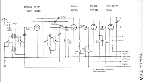
- TRF with regeneration; 1 Special; 2 AF stage(s); Neutrodyne
- Tuned circuits
- 2 AM circuit(s)
- Wave bands
- Broadcast (MW) and Long Wave.
- Power type and voltage
- Storage and/or dry batteries / 120+4 Volt
- Loudspeaker
- - For headphones or amp.
- Material
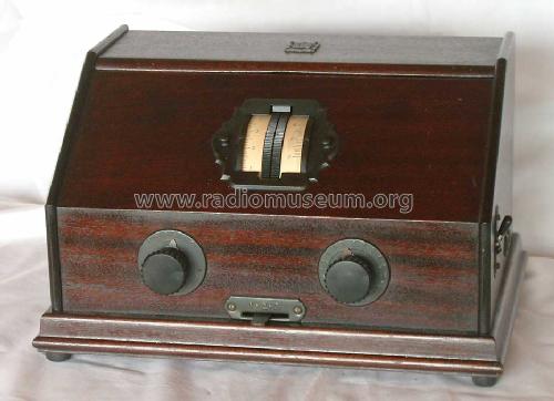
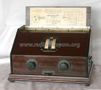
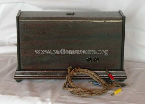
- Wooden case
- from Radiomuseum.org
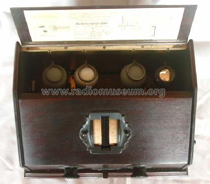
- Model: 4A Batt. - Telefunken Deutschland TFK,
- Dimensions (WHD)
- 330 x 280 x 200 mm / 13 x 11 x 7.9 inch
- Notes
- «frequenzgl.Kond.+NF-Anschl.» [474]
- Source of data
- Kat. Radio-WEB 1929 / Radiokatalog Band 1, Ernst Erb
- Circuit diagram reference
- Lange-Nowisch
- Mentioned in
- Radiokat. Reichsthaler 1930
- Other Models
-
Here you find 3561 models, 3146 with images and 2113 with schematics for wireless sets etc. In French: TSF for Télégraphie sans fil.
All listed radios etc. from Telefunken Deutschland (TFK), (Gesellschaft für drahtlose Telegraphie Telefunken mbH
Forum contributions about this model: Telefunken: 4A Batt.
Threads: 1 | Posts: 1
Die 4A-Geräte konnten alternativ mit Wechselspannung (damals sehr beliebt in Verbindung mit Netzanoden) geheizt werden (analog zu den Geräten T9A, T40A, ...). Dazu waren die Geräte für entsprechende Röhren mit indirekter Heizung vorbeireitet. Die Röhren sind dann 2x REN1104, REN1004 und RE134.
Gruß
Dirk Becker
Gruß
Dirk Becker
Dirk Becker, 16.Mar.04