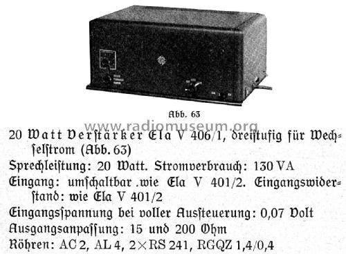
- País
- Alemania
- Fabricante / Marca
- Telefunken Deutschland (TFK), (Gesellschaft für drahtlose Telegraphie Telefunken mbH
- Año
- 1938–1940
- Categoría
- Amplificador de audio o mezclador
- Radiomuseum.org ID
- 4239
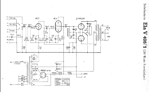
Haga clic en la miniatura esquemática para solicitarlo como documento gratuito.
- Numero de valvulas
- 5
- Válvulas
- AC2 AL4 RS241 RS241 RGQZ1,4/0,4
- Principio principal
- Amplificador de Audio; 3 Etapas de AF
- Gama de ondas
- - no hay
- Tensión de funcionamiento
- Red: Corriente alterna (CA, Inglés = AC) / 110-220 Volt
- Altavoz
- - Este modelo usa altavoz exterior (1 o más).
- Potencia de salida
- 20 W (unknown quality)
- Material
- Metálico
- de Radiomuseum.org
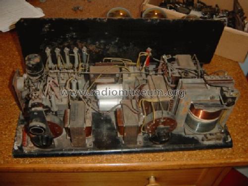
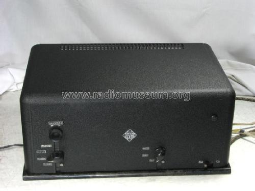
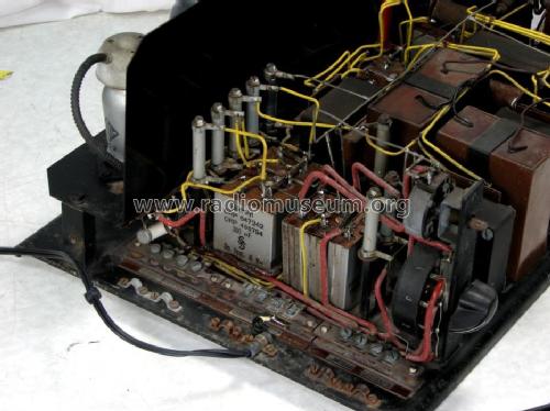
- Modelo: Ela V 406/1 - Telefunken Deutschland TFK,
- Forma
- Sobremesa de cualquier forma, detalles no conocidos.
- Ancho, altura, profundidad
- 460 x 215 x 320 mm / 18.1 x 8.5 x 12.6 inch
- Anotaciones
- Peso neto
- 18.5 kg / 40 lb 12 oz (40.749 lb)
- Precio durante el primer año
- 540.00 RM
- Procedencia de los datos
- Handbuch WDRG 1938 / Radiokatalog Band 1, Ernst Erb
- Referencia esquema
- Lange + FS-Bestückungstabellen
- Otros modelos
-
Donde encontrará 3573 modelos, 3159 con imágenes y 2114 con esquemas.
Ir al listado general de Telefunken Deutschland (TFK), (Gesellschaft für drahtlose Telegraphie Telefunken mbH
Colecciones
El modelo es parte de las colecciones de los siguientes miembros.
Contribuciones en el Foro acerca de este modelo: Telefunken: Ela V 406/1
Hilos: 1 | Mensajes: 1
Hallo,
bei der Ansicht des Schaltplanes zum Telefunken Ela V 406/1 ist mir ein Fehler
aufgefallen. Der Kondensator parallel zum 80 Ohm Widerstand (- 3 V Anschluß)
darf nicht 300 pF sondern muss 300 µF / 6 V sein.
Wenn gewünscht, stelle ich den geänderten Schaltplan gern ein.
Mfg Peter Nitzschmann
Anexos
- Schaltplan (170 KB)
Peter Nitzschmann, 31.May.09
