Antenna Amplifier TRV
Teleste; Turku
- País
- Finland
- Fabricante / Marca
- Teleste; Turku
- Año
- 1967
- Categoría
- Amplificador de Radiofrecuencia
- Radiomuseum.org ID
- 283818
- Numero de transistores
- Hay semiconductores.
- Semiconductores
- Principio principal
- Amplificador de RF (solamente)
- Gama de ondas
- Bandas de recepción puestas en notas.
- Tensión de funcionamiento
- Red: Corriente alterna (CA, Inglés = AC) / 220 Volt
- Altavoz
- - - No hay salida de sonido.
- Material
- Metálico
- de Radiomuseum.org
- Modelo: Antenna Amplifier TRV - Teleste; Turku
- Forma
- Chasis (tambien de autoradio)
- Ancho, altura, profundidad
- 435 x 265 x 65 mm / 17.1 x 10.4 x 2.6 inch
- Anotaciones
-
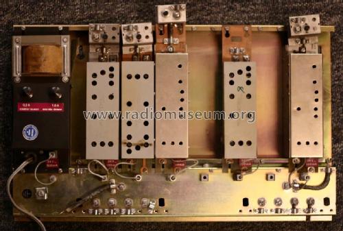
Teleste second generation antenna amplifier. Transistorized,
Chassis versions:
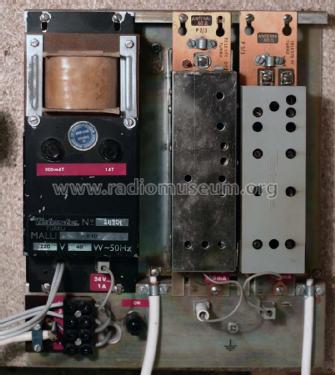
- 2 modules 210 x 265 x 65 (purpose: add mode channels, eg. UHF channelconverterrs, to existing tube amplifier systems)
- 7 modules 435 x 265 x 65 mm
- TVS-24K. A single channel power supply (6,3VAC in, -24VDC out. To add UHF channel converter into a tube amplifier chassis
Modules:
- V-10 Power supply -24V (2 versions, later one with axial electrolytics)
- TRU-40 (FM band 87-108 MHz
- TRV-xxyy (TV VHF band, xx: channel number, yy: gain
- TRUK-xx/zz (TV UHF channel converter. xx=input channel, zz=output channel VHF)
- attenuators, band-pass filters, band reject filters etc.
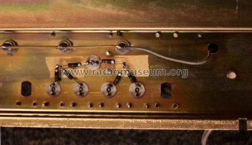
Chassis has resistive built-in power splitterr for 75 ohm antenna network. Not recommended for new installs, because of too low attenuation between networks and poor performance in UHF band.
- Mencionado en
- - - Manufacturers Literature (Telste history, page 34)
- Autor
- Modelo creado por Matti Adolfsen. Ver en "Modificar Ficha" los participantes posteriores.
- Otros modelos
-
Donde encontrará 17 modelos, 16 con imágenes y 8 con esquemas.
Ir al listado general de Teleste; Turku
Colecciones
El modelo Antenna Amplifier es parte de las colecciones de los siguientes miembros.


