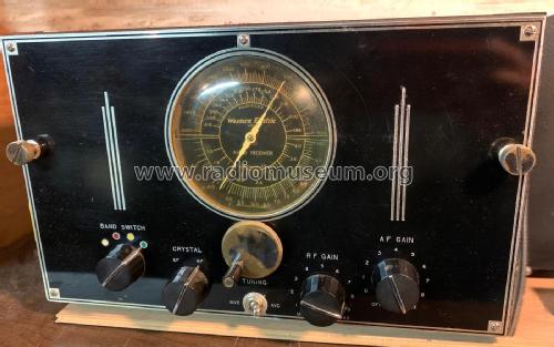
20A aircraft receiver base station version
Western Electric Company Inc.; New York (NY)
- Country
- United States of America (USA)
- Manufacturer / Brand
- Western Electric Company Inc.; New York (NY)
- Year
- 1936 ?
- Category
- Amateur-Receiver (amateur bands, may include broadcast bands)
- Radiomuseum.org ID
- 314656
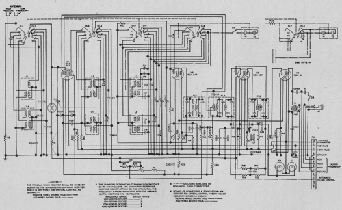
Click on the schematic thumbnail to request the schematic as a free document.
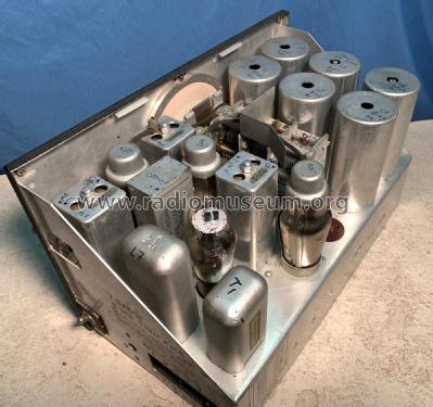
- Number of Tubes
- 4
- Main principle
- Superhet, IF regeneration; ZF/IF 96 kHz; 2 AF stage(s)
- Tuned circuits
- 2 AM circuit(s)
- Wave bands
- Broadcast, Long Wave and 2 x Short Wave.
- Power type and voltage
- Powered by external power supply or a main unit. / 200 vdc & 12 vdc Volt
- Loudspeaker
- - For headphones or amp.
- Material
- Metal case
- from Radiomuseum.org
- Model: 20A aircraft receiver [base station version] - Western Electric Company Inc.;
- Shape
- Miscellaneous shapes - described under notes.
- Dimensions (WHD)
- 13 x 8 x 9 inch / 330 x 203 x 229 mm
- Notes
-
Amelia Earhart used this model aircraft radio receiver on her ill-fated 1937 flight from New Guinea to Howland Island in the Pacific. It was available in the base station configuration you see here. With the face plate removed, a mechanism could be installed that made it possible to control the radio from the cockpit by mechanical remote control. Some say that the shortcomings of this radio contributed to the failure of the flight.
The manufacturer's intention was to create a radio that was compact and light weight. They did several things to accomplish this. They used a 6F7 dual function tube that served as both an RF and IF amplifier. They included regeneration to increase gain. They used a 6B7 tube that served four functions (IF amplifier, 2nd detector, AVC), then after demodulation the audio signal was passed through the tube again for amplification. The circuit was very compact and difficult to trace and troubleshoot. The compactness could lead to internal feedback problems.
The output was through headphones and required two antennas. (high and low frequencies). The output tube was a type 41. The power requirement was 200 VDC and 12 VDC provided by a generator run by one of the engines.
The case is a rectangular aluminum box (removed in photos).
- Net weight (2.2 lb = 1 kg)
- 15 lb (15 lb 0 oz) / 6.810 kg
- Literature/Schematics (2)
- - - Manufacturers Literature
- Author
- Model page created by Ron Boucher. See "Data change" for further contributors.
- Other Models
-
Here you find 171 models, 150 with images and 32 with schematics for wireless sets etc. In French: TSF for Télégraphie sans fil.
All listed radios etc. from Western Electric Company Inc.; New York (NY)
Collections
The model 20A aircraft receiver is part of the collections of the following members.