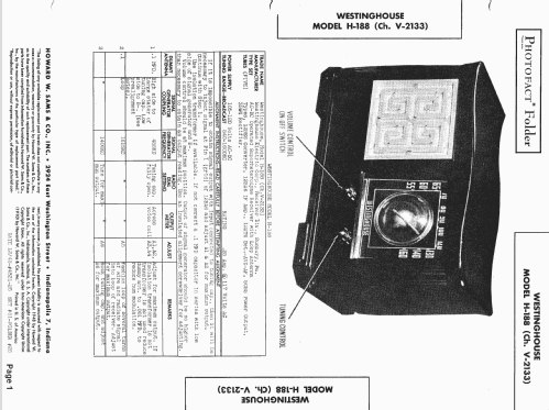
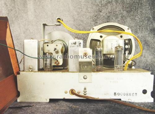
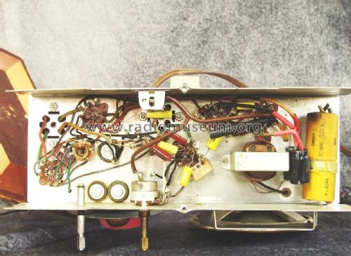
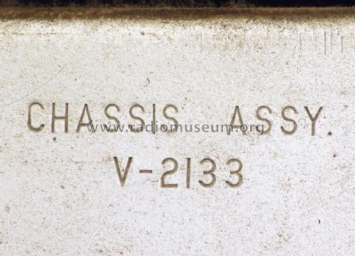
H-188 Ch= V-2133
Westinghouse El. & Mfg. Co. - see also Canadian W.
- Country
- United States of America (USA)
- Manufacturer / Brand
- Westinghouse El. & Mfg. Co. - see also Canadian W.
- Year
- 1949 ?
- Category
- Broadcast Receiver - or past WW2 Tuner
- Radiomuseum.org ID
- 77691
-
- alternative name: Westinghouse El. Int.
Beitman

Beitman


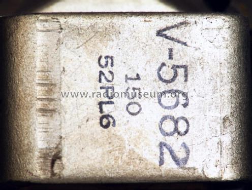
Print on speaker magnet
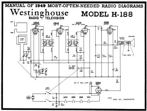
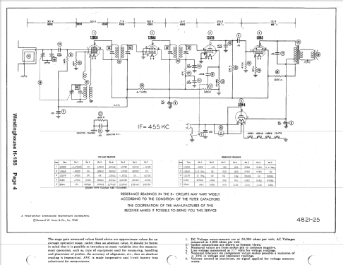
Click on the schematic thumbnail to request the schematic as a free document.
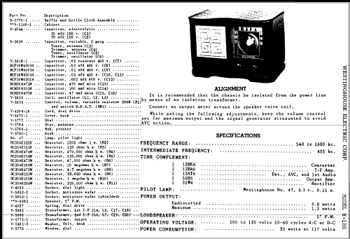
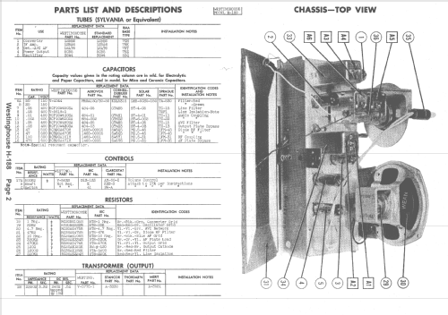
- Number of Tubes
- 5
- Main principle
- Superheterodyne (common); ZF/IF 455 kHz; 2 AF stage(s)
- Tuned circuits
- 6 AM circuit(s)
- Wave bands
- Broadcast only (MW).
- Power type and voltage
- AC/DC-set / 105 - 120 Volt
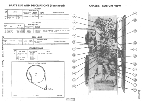
- Loudspeaker
- Permanent Magnet Dynamic (PDyn) Loudspeaker (moving coil) / Ø 5 inch = 12.7 cm
- Power out
- 0.8 W (unknown quality)
- Material
- Plastics (no bakelite or catalin)
- from Radiomuseum.org
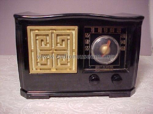
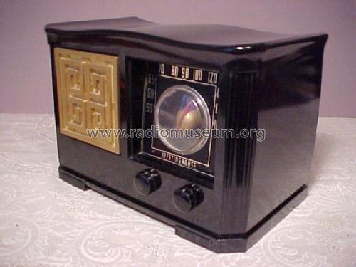
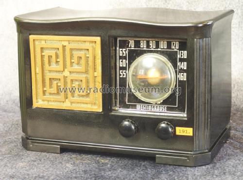
- Model: H-188 Ch= V-2133 - Westinghouse El. & Mfg. Co. -
- Shape
- Tablemodel, with any shape - general.
- Source of data
- Collector's Guide to Antique Radios (6th edition)
- Circuit diagram reference
- Rider's Perpetual, Volume 19 = 1949 and before
- Mentioned in
- Photofact Folder, Howard W. SAMS (4821-25 Set 51 Folder 25)
- Literature/Schematics (1)
- Beitman Radio Diagrams, Vol. 09, 1949
- Author
- Model page created by Walter Wiesmüller † May 2012. See "Data change" for further contributors.
- Other Models
-
Here you find 3151 models, 1749 with images and 2665 with schematics for wireless sets etc. In French: TSF for Télégraphie sans fil.
All listed radios etc. from Westinghouse El. & Mfg. Co. - see also Canadian W.
Forum contributions about this model: Westinghouse El. &: H-188 Ch= V-2133
Threads: 1 | Posts: 4
Hi everybody,
I am in the process of re-capping a Westinghouse H-188 and all has gone well up to now, they seem to have relatively few capacitors and straightforward electrolytics.
However, one of the capacitors (0.05mfd at C7 on the schematic) is marked as "resonant" can I replace this with a standard 0.05mfd polyester capacitor, or is there something else needs to be done?
I know this is an American radio and runs on 105 - 120 volts.
Please forgive my niaive question, but I am relatively new to vintage radio restoration.
Many thanks.
Anthony Taylor, 05.Sep.13