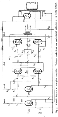
Williamson Amplifier
Wireless World; London
- País
- Gran Bretaña (GB)
- Fabricante / Marca
- Wireless World; London
- Año
- 1947
- Categoría
- Amplificador de audio o mezclador
- Radiomuseum.org ID
- 340002
Haga clic en la miniatura esquemática para solicitarlo como documento gratuito.
- Numero de valvulas
- 7
- Gama de ondas
- - no hay
- Tensión de funcionamiento
- Red: Corriente alterna (CA, Inglés = AC)
- Altavoz
- - Este modelo usa altavoz exterior (1 o más).
- Material
- Metálico con lámparas a la vista.
- de Radiomuseum.org
- Modelo: Williamson Amplifier - Wireless World; London
- Forma
- Chasis (tambien de autoradio)
- Anotaciones
-
Design for a High-Quality Amplifier.
By D. T. N. Williamson (1923-1992)The Williamson amplifier is a four-stage, push-pull, Class A triode-output valve audio power amplifier designed by D. T. N. Williamson during WW2.
He published the design in Wireless World in May 1947, and it soon set the standard of high-fidelity sound reproduction and served as a benchmark or reference amplifier design throughout the 1950s.The original circuit was copied by hundreds of thousands of amateurs worldwide. It was an absolute favorite on the DIY scene of the 1950s, and at the beginning of the decade also dominated British and North American markets for factory-assembled amplifiers.
The Williamson circuit was based on the Walter Cocking designs in 1934 & 1946 Wireless World amplifiers.
The design elements of a “Williamson” Amplifier are:
1. Four stages, input voltage amplifier, phase splitter, driver, and output all operating in triode mode. The output valves may be triode, beam tetrode, or even pentode types, but the latter types will be wired in the circuit to function as triodes.
2. The output stage is biased for class-A push-pull operation.
3. The output transformer is of the highest quality and conforms to the specification for primary inductance (min. 100H) and leakage inductance (max. 30mH).
4. 20 dB of feedback is taken from the output secondary to the cathode of the first stage. Feedback of this degree over 4 stages is, as noted in the Radio Engineering Handbook (5e) a ‘severe test of design ‘. [1]
Examples of commercially produced Williamson Amplifiers:
1954 Heathkit Type W-2
1956, Pederson Electronics W-15Examples of Williamson Output Transformers:
Partridge VDN/436B
Ferguson OP25/15
Red Line AF8/2The reprints of the Wireless Weekly Design for a High-Quality Amplifier are available here.
[1] The Williamson Amplifier of 1947 by P.R. Stinson.
- Mencionado en
- Wireless World (The), London (WW, 79) (April 1947 Pages 118-121, May 1947 Pages 161-163)
- Autor
- Modelo creado por Gary Cowans. Ver en "Modificar Ficha" los participantes posteriores.
- Otros modelos
-
Donde encontrará 7 modelos, 5 con imágenes y 6 con esquemas.
Ir al listado general de Wireless World; London

