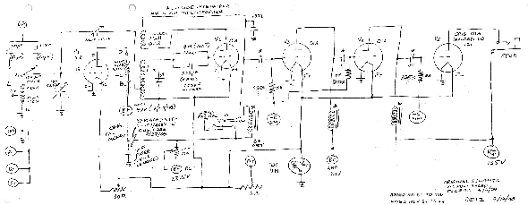
browning: Kit - Traced schematic
browning: Kit - Traced schematic
Dear Radiophiles, Ron Roscoe has traced the schematic for his Browning-Drake Kit receiver from 1928.
This receiver employs positive feedback with opposite goals, the first reduces gain from oscillation conditions in the RF stage, while the other increases gain to a point just under oscillation in the regenerative detector:
First, Miller capacitance neutralization is acchieved with positive feedback applied from the secondary of the output RF transformer to the input grid of the RF triode.
Second, Postive feedback current is fed from the plate circuit of the regenerative detector to reinforce the detection efficiency of grid-leak detection. The non-linear detection characteristic of the grid is one of the steps around the positive feedback loop. The positive feedback sharpens the non-linearity of the grid transfer function that is necessary for detection. Much of the sensitivity that a regenerative detector provides comes from the improved detection efficiency, not just the raw increase in overall gain from PFB.
The coils marked "*" at the audio stage plates are integrated with their coupling capacitors marked "*", in National Impedaformers. This one of several coupling schemes that show up in different versions of this kit.
I repaired the National Impedaformer for Ron. I melted out the wax and added a 0.1uf coupling cap, while disconnection one end of the existing cap. The choke was open at it's solder connetions, so it was easy to repair it.
Rivets were drilled out. Heat gun melted out the wax
Just enough heat was used to melt wax. Insulating paper pieces, and integral 0.1uF capacitor.
Grid bias resistor holder visible at the top could be used only for first stage, where zero volts bias was consistent with small audio signals. The wooden coil bobin was removed from the core by twisting the laminations.
Regards,
-Joe
To thank the Author because you find the post helpful or well done.
Schematic updates
Hello Radiophiles,
I have updated schematics for Ron's Browning Drake. These were taken from photographs. The quality is poor, but useable.
Regards,
--Joe
November 8th, 2009: Schematics updated yet again with scans sent by Ron Roscoe. The schematic content is the same, but the graphic quality is much improved.
Regards,
-Joe
To thank the Author because you find the post helpful or well done.
Browning-Drake in one sheet.
I have stitched together Ron's two scans of his hand-traced Browning drake schematic. This schematic is best printed in double size format paper, like American size B 11"x17".
Click to enlarge and save.
Thank you Ron Roscoe for the very nice scans.
Regards,
-Joe
To thank the Author because you find the post helpful or well done.
RF supply and neutralizaiton.
Ron Roscoe contacted me to point out that the original power supply connection for the RF front end was incorrectly tied to the low voltage 22.5V supply of the detector stage, as shown in post 1.
Ron moved the RF stage supply to the appropriate 90V supply as shown in post 2.
It is possible that a previous owner connected the RF stage supply to the low voltage to kill the RF stage gain and avoid oscillations. This could have been motivated by lack of knowledge about how to neutralize the RF stage with the "neut. cap".
Now, with the RF plate at 90V and "neut. cap" properly adjusted, the RF stage gives a substantial gain without oscillations.
A related Neutralization problem:
Ron and I both own FADA 160 4 tube Neutrodyne reflex battery sets. We found that both radios had the neutralization variable capacitors soldered in place in the minimum capacitance position. In other words, our FADA's were not neutralized, despite the licensing feed paid to Hazeltyne for the use of the Neutrodyne technique. Both radios had an annoying tendency to oscillate.
I removed the solder from the variable tubular glass neutralization capacitors, and adjusted them for minimum coupling from the plate to the grid. This was done with an RF generator driving the plate at 1MHz, while a scope monitored the net coupling at the grid of the same stage.
The tubes were in place, but the power was off. The neutralization was complete when a minimum coupling from plate to grid was achieved.
I have not heard my FADA oscillate since.
Regards,
-Joe
To thank the Author because you find the post helpful or well done.


