cirkit: G3WPO DIP Oscillator /WaveMeter Operations
cirkit: G3WPO DIP Oscillator /WaveMeter Operations
If you search on "Dip Meter" on RMorg you may find 60 pages of results. My first meter was something like this Leader (link) in about 1981. Joe Sousa suggested I write something as the "Dip meter use" is almost like a lost art today. I left the Leader Transistor Dip Meter behind when I moved in 1983.
Originally called a Grid Dip Meter or GDO (Grid Dip Oscillator) when they used a valve (tube), the name has stuck and often bipolar or Transistor or FET Dip Meters are also called "GDO".
The principle is simply to have an oscillator where the tuning coil is external and easily influenced by coupling to another tuned circuit. A diode detector feeds a meter so the oscillator level is visible. If an external tuned circuit is at the same frequency then some of the oscillator power will couple to it and the meter needle will dip as you move the tuning capcitor past the resonance. The meter can thus be used to tune aerial "traps", IF filters and loop aerials. If the oscillator is too powerful or stable then the dip will be too small. This is why the main tuned circuit is usually on the grid, base or gate of the amplifier.
Band switching is just manually using a different plug in coil.
Today with cheap 0.01% or better frequency meters that work 100kHz to 2GHz a good option is an FET buffer on the oscillator to drive a counter for accurate frequency display. This output can also be used as a "cheap" RF signal gernerator.
Most meters have a mode where the oscillation is disabled. This is traditionally called a "wavemeter". It's nothing more than a single tuned "crystal radio" or TRF with a meter replacing the headphones!
One problem is that without a band dependent oscillator gain control the oscillator can be too strong on the lower bands and thus little or no "dip". The G2WPO mk1 suffers badly from this which is largely mitigated on the mk2 by using dual gate FETs and a gain set resistor on each plug in coil.
To thank the Author because you find the post helpful or well done.
Aligning old IFT
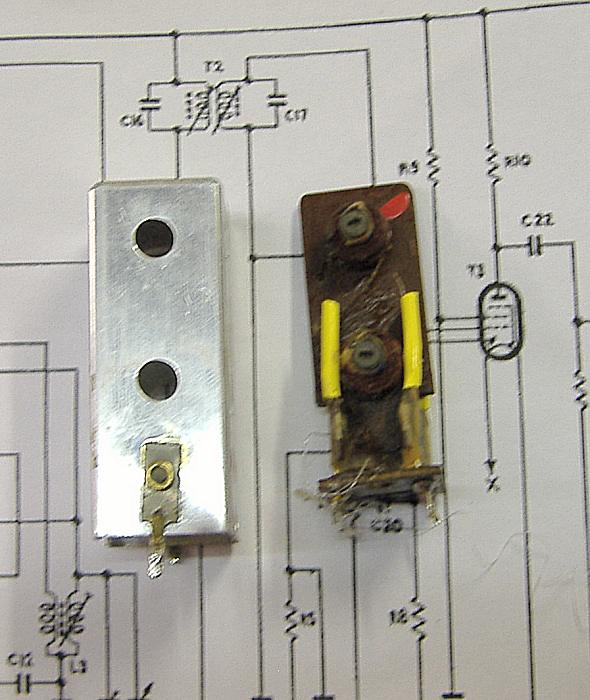
Here is example of old double tuned IFT. They are widely separated to allow small coupling and tuning both coils. Under coupled and you have too broad a response and lower level. Too close and you get a double peak. Fortunately the separation isn't adjustable.

The assembly is T2, C16 and C17 on the schematic
But the G3WPO Dip Meter is useless really even at 7MHz in Dip sensitivity. How to align 470KHz coils with it?
First a 50 Ohm signal generator connected directly would be the wrong impedance. The Anode impedance of pentode driving the IFT is high and the grid load impedance of next stage is also high. With an IFT from 1970s on transistor there is only one tuned circuit and we would not be having to rebuid it.
First with aid of a box of old coils and a frequency counter we make a coil with 100pF capacitor across it for dual purpose of lower frequency and "bandspread". We have easily 415kHz to 475kHz using a 100pF "padding" capacitor. But we get no dip...
We must not connect anything that would load the tuned circuits. We place the Dip Meter about 2 to 3cm from the coils (equidistant) connect 10:1 scope probes to both coils. On the Dual channel scope we can then peak both coils and see the interaction. A counter on the Dip Meter buffer output verifies the meter isn't pulled or drifting off 470KHz.
Of course if you had a meter that was sensitive at 470KHz the scope isn't needed! It's important to have as much separation as possible with the tuned circuit under test so as to not pull it off frequency.
RF Alignment
The Dip Meter can be a handy signal generator. For the radio sets with long wire put a few loops near the plug in coil to pick up the signal. With a set with a loop aerial or ferrite rod make sure the Dip meter isn't too close. About 150mm (6") may be fine. In the 1950s a workshop would have had a suitable loop that could be driven by a bench signal generator. But the Dip Meter is actually ideal.
If it's a tuned loop on the radio set (and all good ones and alll battery sets were RF tuned) and the Dip meter isn't a G3WPO, but one sensitive on the desired band, then even when the radio is off the radio tuning will "dip" the meter at desired calibration points.
To thank the Author because you find the post helpful or well done.