Decca Navigator - Continuous- Wave Navigation System
Decca Navigator - Continuous- Wave Navigation System

DECCA NAVIGATOR
Continuous-Wave Navigation System
Wireless World March 1946.
It is well known that if the distance of a ship from each of three known fixed points, or the bearings of two fixed points from the ship, can be found the position of the ship relative to these points is completely determined. The measurement of the bearings is the basis of normal position-finding by directional reception. With ordinary DF equipment, the operator in the ship takes bearings on two or more signals of known and fixed origin and the ship's position is easily calculated from these figures.
More recently distance measurement has come to the fore, largely because it is possible to measure distance more accurately than bearing by using the pulse technique of radar. The Gee system operates on this principle and proved its value during the war. The disadvantage of a pulse system is that it occupies a large frequency band. Sharp pulses are necessary for accurate range measurement and sharp pulses mean a large bandwidth. This in turn means a high operating frequency and this again means that the useful range is limited. The really high frequencies most suited to pulse work are limited substantially to ranges within the visual. This places a limit of 20-50 miles range at sea level, depending on the height of the transmitting aerials. For air navigation much larger ranges are possible, because of the great height of the aircraft, and it was largely this which made Gee usable over the Continent.
The use of lower frequencies permits long ranges to be obtained because of sky-wave reception, but the accuracy is reduced. Skywaves inevitably reach the receiver by a longer path than the direct and so give a false measurement of range. This could be allowed if it were a constant, but in practice, it is usually subject to variation.
If accurate range measurement is to be made at great distances it is necessary to work on frequencies that provide a direct ray and preferably, but not essentially, do not provide any sky wave. This means low radio frequencies of, say, 100 kc/s or lower, depending on the range required. But such frequencies can hardly be used with pulses and some alternative method of measuring range is very desirable.
Such an alternative is used in the Decca Navigator. Only continuous waves, normally unmodulated, are used, and the bandwidth needed is thus negligible.
The range is measured by comparing at the receiver the phase of signals from known spaced stations.
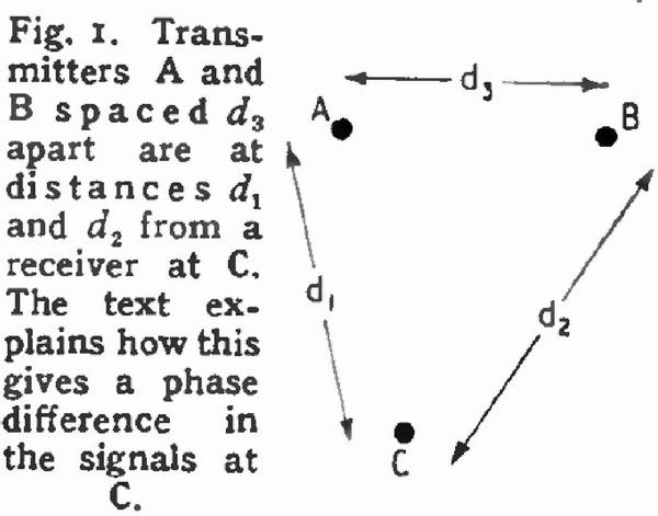
As an example of the basic principle, suppose that there are two, stations A and B in Fig. 1, a distance d3 apart, and that each is radiating a wave of 100 kc/s in the same phase.
 That is to say, at any instant of time when the wave at A reaches its positive maximum that at B also reaches its positive maximum.
If this maximum is imagined traveling outwards from A with the velocity of light it will reach the receiver at C, after a time t1 = d1/c where c is the velocity of light. Similarly, the maximum from B reaches the receiver at t2 = d2/c. At C, therefore, the two waves are not in phase because they have traveled different distances, and the difference in phase is a measure of the difference in distance.
The transit time of one cycle is 1/ƒ = λ/c, so the time intervals representing distances are d1/λ and d2/λ expressed as fractions of a wavelength. In terms of phase, there are 360° to each wavelength so that the phases at C relative to the transmitters are θ1 = 360 d1/λ and θ2 = 360 d1-d2. The relative phase of the two signals at the receiver, which is all that can be measured, is θ1= θ1 - θ = 360 (d1 – d2)λ. The relative phase of the two signals at the receiver is thus a direct measure of the difference in distance from the two transmitters.
It may well be asked at this point how the signals from the two stations are distinguished since they appear to be two continuous waves of the same frequency.
In fact, they are not. The frequencies transmitted are different but have a common harmonic. Thus, A might radiate on 85 kc/s and B on 113.3 kc/s.
The receiver at C receives these signals separately and generates harmonics of each. The fourth harmonic of 85 kc/s is 340 kc/s, and the third of 113.3 kc/s is also 340 kc/s, so in this way, the effect of two signals of the same frequency is produced and it is the phase difference between these harmonics which is actually measured.
This is done by a phasemeter. The signals are applied to discriminators which produce direct currents proportional to the sum and difference of the phases.
These are passed through coils at right angles and a magnet in the field, coupled to an indicating pointer, takes up a position along the resultant. The phase differences can thus be read directly from a dial.
This measurement of the phase difference between the signals from two stations does not enable one to determine one's position, for there are an infinite number of points of equal difference of distance from the stations. It is easy to see that a receiver on a line bisecting at right angles the line joining the transmitters is always at the same distance from each, and hence the phase difference is zero. All that the reading tells one is that one is somewhere on that line.
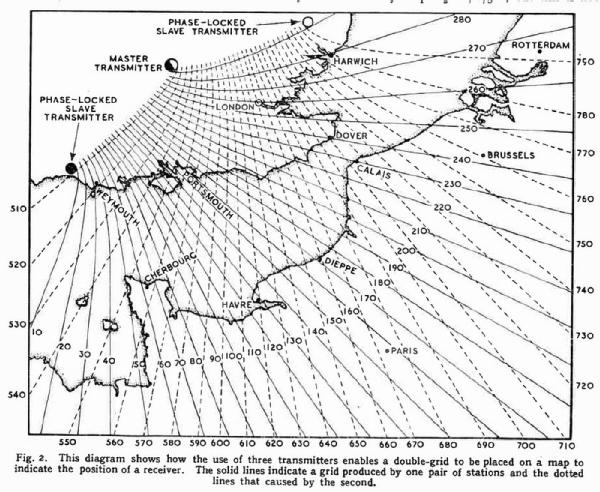
Similar imaginary lines exist for each phase angle and take a hyperbolic form. Such a set of lines can be drawn as a grid on a map or chart and would take the form shown in Fig. 2 by the solid lines. An indicator reading of 240 would then indicate that one was somewhere on a line passing through Dover.

This difficulty is resolved by using a third station, in the example of 127.5 kc/s, in conjunction with the 85 kc/s transmitter. The second harmonic of the one (255 kc/s) and the third of the other are the same frequency, and these two stations lay down a further grid, shown dotted. The receiver is provided with a second phasemeter to measure the phase difference between these signals and the two readings give a definite fix. Thus, if the phase reading is 240 on the solid grid and 710 on the dotted, the two crosses at Dover. For Brussels, the readings are 242 solid and 760 dotted.
There is another point of possible ambiguity. The phase angle does not indicate only one line on the grid, for a given phase angle can represent many differences in distance. The formula given earlier can be written
d1— d2 = θλ/360, but this is not necessarily correct, for the phase difference repeats itself on every wavelength. The addition to θ of 360° makes no difference, so the formula is more correct d1 — d2 = (θ ± 360 n) θλ/360= θλ/360± nλ where n is any integer. A given phase difference thus indicates any number of differences of distance varying by whole numbers of wavelengths.
With a third transmitter, this leads to a number of possible positions. Some of these may be excluded on extrinsic grounds; thus in a surface vessel, any positions on land are obviously ruled out.
In order to overcome this two means are adopted. The first is to start from a known position and keep the receiver operating continuously. The phase difference indicator makes a complete revolution for every wavelength passed through so that a revolution counter attached can indicate the total number of waves passed through and ties the reading down definitely.
This fails, of course, if reception is interrupted and to enable a fix to be obtained at any time, an 85 kc/s signal is periodically transmitted in addition to the normal signals from the other stations. This has the effect of swinging the grid and from the second set of readings, the true position can be obtained.
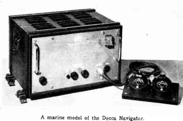
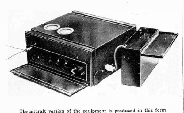
All this sounds very complicated, but the apparatus is actually very simple to use. It consists essentially of three straight re-dials to read correctly by a hand control. The gear is in continuous operation and to find the position at any time it is necessary only to read the dials and refer to the gridded chart. If the initial position is not known or if reception has been interrupted, the operator takes additional readings at a time when the 85 kc/s signal is being transmitted from the other stations, and from this additional data a simple calculation gives the true position.
Reference has been made to the indicators being calibrated in lanes. They actually measure phase difference and one revolution of the main indicator covers
360 degrees. This is called one lane and is subdivided into 100 divisions. The subsidiary dials eared to it as revolution counters read tens and hundreds of lanes.
The lane is thus a purely arbitrary measure and is adopted as more convenient for the non-technical than a calibration in phase angles.


The apparatus is produced by the Decca Navigator Company, a subsidiary of the makers of Decca broadcast receivers and gramophone records.
Wireless World March 1946, pages 93-96
To thank the Author because you find the post helpful or well done.