For Beginners: How a Radio Works Part1
For Beginners: How a Radio Works Part1
This is part 1 of a very simplified series without details like mathematics.
Part 1 A simple Radio
The simplest radio to demonstrate and understand is a "Crystal Radio". A crystal radio has no amplifiers and only one tuned filter.

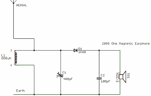
Fig. 1: Schematic of 1920s style Crystal Set with High Impedance headphones (moving iron or moving coil).
The 2000 Ohms earphone acts as resistor to set the capacitor discharge time constant.

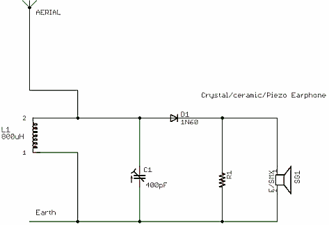
Fig. 2: Schematic of 1930s style Crystal Set with High Impedance Piezoelectric or "crystal" earphone.
The ceramic earpiece is equivalent to a 2nF to 20nF capacitor (depending on Model)
Marconi didn't invent Radio. But he did realise the importance of a wire buried in the earth (Earth) and aerially raised wire (Aerial) as the method of radiating the Electromagnetic waves and letting current flow in the tuned circuit. His Irish mother funded his initial experiments 1894 and he demonstrated the system to Preece of the British GPO in 1897 after correspondence in 1896. Though Thompson and Braun had both discovered or invented the Cathode Ray Tube in 1897 the Amplifying Triode wasn't invented till 1906 by Lee de Forest. The Diode valve or tube in 1904 by John Fleming.
So the era of the "Crystal Set" in the sense of a radio receiver with only Aerial, Earth, Tuned Circuit and passive Detector is really from 1880s till 1906. Scheduled broadcasts of Speech and Music only started in 1921, when the Crystal Set was already obsolete for 15 years. In reality few people listened to the Wireless on Crystal Sets. They where a hobbyist curiosity by the 1920s.
The Crystal set and indeed any radio can be reduced to the following components
- Aerial or Reception system
- A filter mechanism to receive just one transmission.
- A detector to convert the transmitted signal into the original information content (Voice, data, Video or whatever)
- An output device to hear and/or see the transmitted information
Even a "USB dongle" + laptop for Internet or Digital TV conforms to this model.
1. Aerial or Reception system.
The simplest at low frequencies is a long wire Aerial and connection to metal buried in the ground for an Earth. At high frequencies the cabinet of the radio can be the earth and single rod 1/4 of a wavelength long (8cm approximately for GSM band of 900MHz, it would be 37,500cm at Long Wave). This connects to the next section.
2. A filter mechanism to receive just one transmission.
The simplest kind is a coil "L2" and a capacitor "C1"which forms a parallel resonant circuit. If it used perfect components it would look like a short circuit at every frequency except the desired one and open circuit for the transmission you want. Transmissions are selected by varying the coil or the capacitor, or both. Multiple radio bands are managed by switching in different coils. In a crystal set the coil and capacitor for tuning have to be very low loss, high quality or Q. If the coil is made 15cm (6") to 60cm (24") diameter then no separate aerial and earth is needed on Medium wave. The coil is influenced by the magnetic component of the Electromagnetic waves (Radio Signal). In contrast a long wire on Medium Wave or a "Whip" (rod) aerial on VHF is being influenced by the electric field component of the Electromagnetic waves. The filter connects to the next section
3. A detector to convert the transmitted signal into the original information content (Voice, data, Video or whatever).
The simplest detector only works for A. M. (Amplitude, CW keyed or ASK / OOK [Amplitude Shift Keying/ On Off Keying]). However a second tuned circuit can convert F.M. or FSK (Frequency Shift Keying such as RTTY) into an AM signal. It's the diode or rectifier as used to convert AC mains to DC. If the amplitude of the AC changes slowly, the resultant DC will vary. You need a capacitor as a low pass filter to remove the AC ripple and a resistor as a load or else the capacitor would charge to the peak of the signal. The principle of a Crystal or Diode detector on a Radio tuned circuit is identical. The Frequency is higher 60KHz to 30MHz rather than 50Hz or 60Hz and the variations of the Audio may vary from 20Hz up to 10KHz on AM bands.
On Fig.1 the "load" resistor is the headphones so there is a capacitor "C2" much larger value than the RF tuning capacitor, the quality isn't so important and the value is large enough to look like nearly a short for the RF (low impedance) but almost open (high impedance) for the 10KHz of Audio. On Fig 2. the "piezo" earpiece (modern ones are ceramic disc on a metal disc, like a "beeper") is the capacitor (About 2nF to 20nF) and thus only a separate resistor "R1" is needed. The detector feeds the output device.
In both cases the diode (crystal detector) charges the capacitor (C2 or ceramic earpiece) from the RF signal and the resistor (R1 or magnetic 2 K Ohm earphones) discharges the capacitor fast enough so the highest modulation frequency isn't affected too much. With a larger resistor or capacitor a voltmeter would be a measure of signal strength as the voltage won't change fast enough to follow the audio signal. This principle is used in more advanced "superhetrodyne" or Superhets to equalise the loudness between strong and weak stations (AGC = Automatic Gain Control or older name is AVC = Automatic Volume Control)
The original "Crystal Detector" was a piece of Galena with a wire poked on a crystal on it. This formed a PN junction, or a basic semiconductor diode. Various semiconductors were investigated in 1800s to 1904/1906 when Valves/Tubes largely "took over". Selenium, Germanium, Copper Oxide and Tellurium compounds all in use by 1930s and Silicon also by 1940s. But even though germanium diodes widely available after WWII, it was simple and in-expensive to add a thermonic diode element to a Triode or pentode valve for combined detector preamp (EABC80, DAF91, DAF96) though by 1955 an AM/FM valve radio (especially a portable battery model) may use a pair of Germanium diodes for the FM detector. Common types of Germanium diodes good for a "Crystal Radio" are 1N34, 1N60 (best), OA47 and OA81. A silicon diode is about 0.6V to turn on compared with 0.1V for a Germanium, so are less sensitive. A signal type Schottky Silicon diode is 0.3V to 0.4V at low currents, still not as sensitive.
4. An output device to hear and/or see the transmitted information
The simplest is a piezo earpiece. Just a ceramic disc on usually a thin brass backing disc. A connection is made to each side.
Real Broadcast Receivers
Early receivers used two, three or more valves (tubes) simply to amplify and detect. The TRF (Tuned Radio Frequency)
- RF amplifier / Detector and Audio amp
- RF amplifier and Detector / Audio amp
- RF amplifier, Detector/Preamp and Audio amp
Usually sets with a Loudspeaker (typically an external Horn loaded earphone mechanism) used four valves. Often there was adjustable positive feedback on the RF amp to lower the losses in the Tuned Circuit and increase selectivity and gain. These "regenerative" sets are trickier to tune.
Edwin Armstrong invented the Regenerative, Superhetrodyne (Superhet), super-regenerative and FM Radio designs in 1914, 1918,1922 and 1930s respectively. By the 1930s (only 10 years after start of consumer broadcast) the Superhet was popular and TRF fading into history.
The TRF is essentially an amplified crystal set. Some had a 2nd or even 3rd RF tuned circuit separated by an Amplifier valve (tube) in each case. On the next Article the Superhet will be explained.

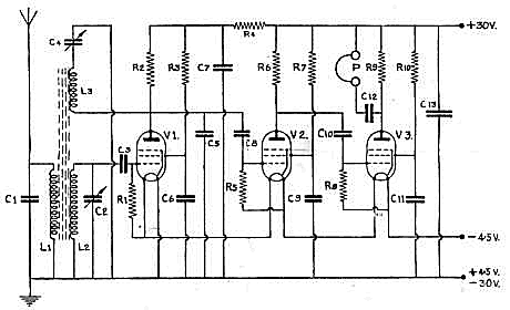
Fig. 3: "Sweetheart" WWII Covert Regenerative "TRF" Receiver.
Operation of Sweetheart TRF Receiver
A wire aerial and an earth connection to metal post or water pipe is the Aerial and Earth on C1/L1 which is a broad resonant circuit. This is coupled by adjustable dust iron or ferrite core to L2 & C2 which tunes to the station. Thus C1, C2, L1 and L2 are equivalent to the coil and capacitor of the Crystal Set. L3 is "regenerative" feedback (i.e. positive) from the output of pentode V1. (A 1940 1T4). C4 adjusts the amount of feedback, too little and the radio is insensitive and poor selectivity. Too much and the RF amplifier will oscillate, and the aerial wire transmits the signal! Bad when you are hiding from Gestapo in a Norwegian ditch listening for coded commands on the BBC. So the "regen" control is tricky. V1 thus acts as RF amplifier and Detector.
The principle is that the amount of Regenerative feedback cancels the loss in L2 and C2 (mostly L2 as C2 is a quality air spaced type). C5 is RF removal low pass filter and R5 "load" as on output of detector diode of a "Crystal Set". V2 and V3 are audio amplifiers to drive the piezo or crystal earpiece "P". The HT is only 30V, a pair of 15V B121 batteries as used in Hearing Aids and test meters on Ohms Range. The 4.5V is the flat torch battery with three cells and a pair of brass strips on top. Both types are now rare, but actually still made. The valves (tubes) are all 1T4, a miniaturised 7 pin version (B7G) of the late 1930s Octal 1.5V Battery valves. It was released by RCA in early 1940. Later made in Europe as DF91. Replaced in early to mid 1950s by DF96 which likely ceased production in 1960s. Russian 1j24b or 1j29b or similar are made till 1991 and are very cheap, but not pin or heater filament compatible.
(c) 2011, 2012 Michael Watterson. All rights reserved. Permission to Radiomuseum.org to display on website
To thank the Author because you find the post helpful or well done.