korting: 1047; Novum

ID: 190288
? korting: 1047; Novum 
22.May.09 01:15
0

Paul E. Pinyot † 2013 (USA)
Articles: 187
Count of Thanks: 17
Paul E. Pinyot  † 2013


Gentlemen,
I have a Korting 1047 Delmonico in for restoration.   There is a small ferrite slug that moves with the FM band.  I need to know:
 
1)  How the dial cord is attached to the shaft of the variable capacitor? 
 
 
1a) There is a little coil spring (12 x 3 mm) that has been included with this radio.  Does this attach to the take up end that is wound around the shaft?
 
 
2) Is the slug engaged with the coil when the FM indicator is maximum or minimum frequency?
 
 
3) What is the exact function of this variable inductor?
 
Thank you,
Paul.
 
More pictures on the bottom of page:


UPDATE - I restrung the variable inductor slug with out the little coil spring.  The slug draws in as the FM band goes down in frequency.

To thank the Author because you find the post helpful or well done.

 2
korting: 1047; Novum  
22.May.09 05:30

Omer Suleimanagich (USA)
Articles: 431
Count of Thanks: 21
Omer Suleimanagich

 3
? Need FM alignment in English. 
28.May.09 05:25

Paul E. Pinyot † 2013 (USA)
Articles: 187
Count of Thanks: 10
Paul E. Pinyot  † 2013

Gentlemen,

I have fully restored this chassis and got through the AM alignment section by using other radio model procedures. I have rebuilt all three Electrostatic tweaters.  WOW what a sound.  Nice and strong.  Great treble and powerful bass.  I am always impressed with the clean powerful sound of these European radios.
 
But I am not satisfied with my FM alignment.
 
I find it rather difficult translating German to English or making a reasonable cross reference between the different radios printed in English and this particular FM tuner. In short, “it just does not feel correct”.
 
Could some one provide an English Alignment procedure or direct me to a similar chassis that employs the same FM tuner with the alignment in English? I would consider purchasing proper documentation if available. Sam’s Publishing only has a schematic with out the alignment procedure.
 
Thank you in advance,
Paul.

To thank the Author because you find the post helpful or well done.

 4
Circuit diagram manual 
28.May.09 07:44

Georg Beckmann (D)
Editor
Articles: 442
Count of Thanks: 15
Georg Beckmann

Hi Paul,

it seems that you have the german docs to this radio. Would it be possible to upload this here in the RADIOMUSEUM.

Because this is missing. If you can't do it, I can assist you.

If you send me the an email with the scans of the German alignment advise, I can translate it, so that you can work with it.

Greetings from Germany


Georg

To thank the Author because you find the post helpful or well done.

 5
Using the Bremen alignment chart for the FM tuner. 
28.May.09 17:24

Paul E. Pinyot † 2013 (USA)
Articles: 187
Count of Thanks: 16
Paul E. Pinyot  † 2013

Geog,

 You are very gracious to offer to translate. I have been using the procedure from the Bremen 821  http://www.radiomuseum.org/r/korting_bremen_82106.html . The Bremen has each FM tuner slug and trimmer capacitor clearly identified.
 
I am having the most difficulty with the FM alignment table (chart). Specifically the last two columns of instructions on the right.  I have NO problems with the AM section. 
 
I made a request for the schematic and was hoping some one would post the proper documents. If I could cut and paste the Bremen text into the Google Translator I would. But the text is a picture and not ASCII code.
 
I appreciate you help!
Paul.

To thank the Author because you find the post helpful or well done.

 6
first trial 
28.May.09 22:50

Georg Beckmann (D)
Editor
Articles: 442
Count of Thanks: 15
Georg Beckmann

Hi Paul,


here a first trial. I didn't find the procedure, how to do the decribed damping of the various resonat circuits, perhaps a parallel resistor.


Georg

Attachments:

To thank the Author because you find the post helpful or well done.

 7
Thank you 
28.May.09 23:29

Paul E. Pinyot † 2013 (USA)
Articles: 187
Count of Thanks: 13
Paul E. Pinyot  † 2013

Georg,

That is beautiful!  Thank you.  I will try this alignment soon.  I saw some dampening in an other procedure.  I will employ that dampening method.

Thanks again,

Paul.

To thank the Author because you find the post helpful or well done.

 8
Whats damping on if-align. 
29.May.09 00:05

Hans M. Knoll (D)
Editor
Articles: 2165
Count of Thanks: 16
Hans M. Knoll

Hello friends.

our member olaf have shows two AM and one FM align.

AM 1and 2

#1  

#2

and FM


on second  part (AM) you can see, whats damping
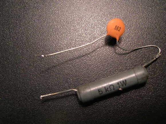
 

and how to do!

hans

To thank the Author because you find the post helpful or well done.

 9
Hans to the rescue 
29.May.09 01:30

Paul E. Pinyot † 2013 (USA)
Articles: 187
Count of Thanks: 15
Paul E. Pinyot  † 2013

Hans to the rescue,

Those are helpful links. I sent the link into the Google Translator and now have a useful supplement to Georg’s translated table. I am in the shop at this time and will attempt the alignment tonight. I will let you know how it goes.
 
Update - It is 2300 hrs here in Pittsburgh PA and I have completed the alignment
 
I use a combination of Georg's translation, Olaf's procedures, Korting Bremen 821/06 documents and Korting  Hamburg chassis 25571 schematic for the ECH81 and EBF89 circuitry.
 
The 10.7 MHz IF was the most difficult to optimize.  Finding the electrical points for L14 Zero Crossing adjustment was the most time consuming. The FM tuner was a "Piece of Cake" with Georg's translation!
 
Thank you all whom contributed.  I would prefer the proper procedure for the Korting 1047 US Export.  However, "Beggers can not be Choosers" as the saying goes.
 
RM.org to the Rescue!
 
Thanks,
Paul.

To thank the Author because you find the post helpful or well done.

 10
good thing! 
29.May.09 09:16

Hans M. Knoll (D)
Editor
Articles: 2165
Count of Thanks: 16
Hans M. Knoll

Hello Paul and Georg!


Yes whe can, if whe all  want !

see post # 3 on top !!!!


hans .


To thank the Author because you find the post helpful or well done.