Loftin-White Amplifier
ID: 224639
Loftin-White Amplifier
22.Jul.10 12:53
15994

E.H. Loftin and S.Y. White published their circuit on Radio News January 1929.
Ghirardy's first edition of "Radio Physics Course" was published in 1930. In the 2nd ed. 1932, 10th impression 1942, the following text on Loftin-White circuit is found.

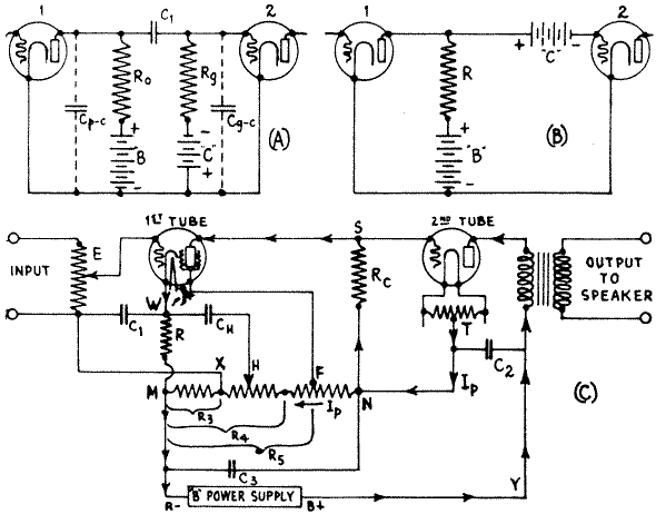
440. The direct-coupled Loftin-White amplifier: In the direct coupled amplifier system the plate of one tube and the grid of the next are coupled directly through a common resistor - no blocking condenser and leak resistor being employed. By eliminating these, grid blocking due to strong signals is avoided and the frequency response is improved. The problem of coupling the successive tubes in vacuum tube amplifiers is largely the problem of causing the plate current variations in the circuit of one tube to cause grid potential variations which are as large as possible and unaffected by the frequency, in the following tube. Of course the proper plate and grid bias voltages must be applied. The so-called "resistance-coupled amplifier" discussed in Article 432, a single stage of which is shown in simplified form at (A) of Fig. 322, really resolves itself into a resistance-capacity coupling by reason of the coupling condenser C, The reactance of this condenser varies with the frequency, and on low frequencies this reactance is sufficiently large to cut down the frequency response. In this type of coupling also, the effective input capacity Cgc between the grid and cathode of the second tube will operate substantially as a shunt across the leak resistance Rg at high frequencies, and will cut the response in the upper range. The plate-cathode capacity Cpc of the first tube acting across the plate resistor Ro also acts the same way. This is larger as the amplification of the tube and associated circuit is increased.
The third fault lies in the fact that there is no voltage step-up in the coupling itself, and thus additional stages are required to secure a desired gain. Also, on strong signals there is a tendency for the grid circuit of the last audio tube to block due to the accumulation of electrons on the grid, and the resulting reduction in the plate current. Direct-coupling schemes have been developed to eliminate the coupling condenser and grid resistor in order to do away with these objectionable frequency-characteristics. This means that a direct coupling between the plate and grid circuits must be employed. Arnold proposed a scheme shown in simple form at (B) in which the coupling condenser and grid resistor were eliminated. The plate of the first tube is conductively or direct-coupled to the grid circuit of the next, through the plate circuit resistor R.
Now let us see what the objections to such a system are. It is seen that a common resistance is used in the plate circuit of one tube and the grid circuit of the succeeding tube. In such a case, the entire positive plate potential, less the drop in the resistance, would be applied to the grid of the next tube. Of course the tube cannot be operated satisfactorily as a distortionless amplifier with a high positive grid potential, so the "bucking" or "C" battery is used in the grid circuit. This battery must of necessity have voltage enough to cancel the plate battery voltage plus whatever grid bias is required. This would all he very well were it not for the fact that in such a circuit the drop across the resistance R, which is common to both these circuits, is not constant. When a signal is applied to the grid of the first tube, its plate current rises, and consequently the drop across the resistance is greater. This upsets the bias on the grid of the next tube, usually sufficiently to throw the second tube off its operating curve. Should the signal get past the second tube, the effect would be even greater in the next stage. Also, in a system of this nature, there is a "drift effect". That is, if for any reason the current through any tube should change, there is no provision made to restore the state of equilibrium. Consequently, after it has been in operation for a moment or so, the various circuit conditions will drift until the entire system is blocked and no signal can find its way through. Also the battery requirements for such a system are impractical.

Fig. 322 Development of the Loftin-White direct-coupled amplifier system.
E. H. Loftin and S. Y. White reduced the direct-coupled circuit to a practical form, eliminating the necessity for the separate "C" battery and adapting the entire amplifier for practical a-c electric operation. A simplified diagram of the essential arrangement in their system is shown at (C). The sources of filament voltages are omitted for simplicity in this diagram. A single source of voltage is used in the plate circuit (shown by the box), and a single coupling resistance R, is employed. The "B" current flows from terminal Y through the plate circuit of the second tube to point T and to N. At point N, the plate current of this tube divides, part flowing through the resistor from N to M, and back to B- and the B+ power supply unit. The other part flows up through coupling resistor Rc to S, and across the plate-cathode path of the first tube to W, then down through resistor R to M - where it joins the other part which came through the resistor from N to M - and back through the "B" power unit. Point M is the most negative point in the entire circuit. The plate current taken by the first tube flowing through the coupling resistor Rc from N to S causes a voltage drop in it, and point S is therefore negative with respect to points N and T by an amount equal to this voltage drop. Hence the grid of the second tube has a negative grid bias voltage with respect to the center point T of its filament circuit, due to this ingenious voltage distribution arrangement. Resistor Rc is constant in value, but the plate-cathode impedance of the first tube will vary when the signal voltage is applied to its grid circuit. There is, therefore, a continually varying change in the voltage distribution between the plate-cathode path of the tube and the coupling resistor Rc when a signal is acting on the amplifier. If the plate impedance is large, the drop across Rc will be comparatively small and vice-versa. When a varying signal voltage is applied to the grid circuit of the first tube, it causes variations in the plate current of this tube: This varying plate current flowing through Rc causes instantaneous variations of the voltage drop across it, which are impressed between the grid and filament of the second tube, and amplified by it. It is evident that the total voltage which must be supplied by the B power unit, is equal to the sum of the effective plate voltages actually on the tubes, plus the grid bias voltage (voltage drop in Rc) of the second tube. This means that for given type of tubes employed, the B power unit in this type of amplifier must be capable of supplying a higher voltage than when ordinary forms of coupling are employed.
The voltage drop from N to M through the total resistor is of course the same as the total voltage drop through Rc plus that from the plate to cathode of the first tube plus that in R, since these, are two parallel circuits. Furthermore, each is equal to the entire B voltage, minus the voltage drop in the second tube. A screen grid tube is usually employed as the first tube, on account of its high amplification factor. Since current flows from N to M, by tapping the resistor at a suitable point F, a suitable positive potential, (with respect to the cathode at W), for the particular plate voltage employed, exists across total resistance R5 and may be applied to the screen grid of this first tube. Resistor R in the cathode-return circuit of the first tube is used as a bias resistor for this. Any tube will have a tendency to increase its plate current when a signal is applied to the grid circuit. As the plate current of the first tube flows through R, the voltage drop across this resistor will tend to increase with the input of the signal. Grid bias resistor R (50,000 ohms for a '24 type tube) for the first tube, is considerably larger than is commonly employed for tubes of this type. There is a definite reason for this. The grid return circuit of this tube is brought back to point X as shown. Point X is at a higher potential than point M by an amount equal to the IR drop in resistance R3 Also point W is at a higher potential than point M, by an amount equal to the IR drop in resistor R; or, stating this another way, M is negative with respect to W. Now by using suitable values of resistance for R3 and R, it is possible to make point M more negative with respect to W, than point X is positive with respect to M. Then, point X will be negative with respect to W and therefore the net bias voltage applied to the grid (which is equal to the difference between these two voltage drops) will be negative with respect to the cathode point W.
Perhaps this may be understood more easily by considering points M, X and W, as three men on three different floors of a building, and considering that lower level is negative and higher level is positive. Man M is on the ground floor. Say man W is on the 10th floor. Then he is positive with respect to M by 10 units. X is on the sixth floor. Therefore he also is positive with respect to M, but only by 6 units. But at the same time he is 10 minus 6, or 4 floors under W, so he is negative with respect to W by 4 units.
In this way, a negative grid bias voltage is applied to the first tube and the grid is kept at practically a constant negative value irrespective of the signal input. Any drift effect is also compensated for by this method. The action taking place is very important.
Referring to the diagram at (C), it will be seen that when, for any reason, an increase occurs in the plate current of the first tube, the bias voltage on the second tube increases automatically due to the greater voltage drop in Rc. This causes a decrease in the plate current of the second tube. This latter plate current constitutes the major portion of the current through the resistor from N to M, so that when it decreases, the voltage drop in the resistor R, decreases. Therefore the net grid bias voltage applied to the first tube increases, tending to keep the plate current of this tube constant. This is the important regulation feature of this circuit.
A condenser CH is connected between the cathode of the screen grid tube and a point H on the voltage divider resistance. The object of this is to introduce a varying hum component voltage into the grid circuit of the tube, of just equal value and opposite phase to that introduced by the varying voltage drop across R caused by any ripple in the plate current, so as to neutralize it and prevent hum. The amount of neutralizating hum-frequency voltage thus introduced, is varied by an adjustable slider H,arranged to be moved along the resistor until no hum appears in the signal output. Under this condition, the varying voltage drop across R due to the ripples in the plate current, are just equal at every instant to the hum-frequency variation in the voltage drop from H to M. Connecting the condenser as shown, makes these hum voltages oppose and neutralize each other in the circuit between the terminals, at every instant. This hum-bucking arrangement is very effective and important and may be applied in any form of amplifier circuit. It enables satisfactory hum-free operation to be obtained even when rather poor filtration exists in the "B" power supply unit, thereby reducing the size and cost of the filter necessary in this unit. By-pass condensers C1, C2 and C3 are connected across the various resistors to prevent undesirable coupling which might take place.
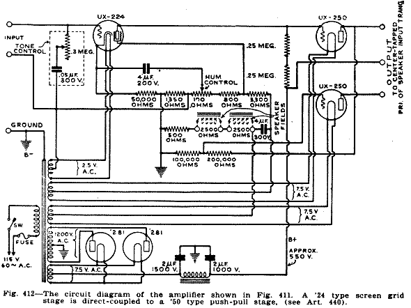
The advantages of the use of this system are cheapness, low weight, low bulk, high gain and the fact that any frequency can be handled with practically no frequency discrimination or wave-form distortion. The amplifying possibilities are limited only by the amplification constant of the tubes. Of course it is advantageous to use a screen grid tube with its high amplification. Due to the high amplification produced, the output tube chosen must have sufficient capacity to handle, without distortion, what the system will apply to it. The output tube is merely a coupling tube between the amplifier and the loud speaker. It must be built to handle power. Even with a single screen-grid tube ahead of it, a large size power tube such as the '50 type should be used in the last stage if the largeamplification of the screen-grid tube is to be used. Otherwise the input or the amplification of the first tube must be materially decreased in order to prevent overloading of the last tube. Usually, lower voltages must be employed on the screen grid tube than are specified in the table of Fig. 214, simply because of the limited grid-swing which the following tube can handle. Thus, when a '24 type tube is followed by a '45 type, since the '45 type can only handle a signal voltage of about 40 volts on its grid, the plate, grid and screen voltages used on the preceding '24 type tube must be less than if, say, a '50 type tube followed. The plate current of the '24 tube under the conditions of operation existing in the usual amplifier of this type is only a few micro-amperes.
Heater types of amplifier tubes are more convenient in the utilization of the voltage distribution existing in the direct-coupled amplifier because the cathodes of the various tubes are independent of each other. With filament types of tubes, the filaments of all the tubes are connected together in the "A" supply, and so it is difficult to apply the voltage distribution system outlined herein. When applying this system to a practical amplifier operated from the a-c electric light circuit, several precautions are necessary in the design.
For instance, even though the filaments of the tubes employed are all designed to operate at the same voltage, say 2.5 volts, it is necessary to operate the filament of the power tube from a separate 2½-volt winding of the power transformer. Any attempt to run this filament from the same 2½-volt winding that operates the heaters of the other tubes will result in trouble. The cathodes of the rest of the tubes are practically at ground potential, or at best, at only a small bias above ground. If, then, we proceed to connect their respective heaters on to the power filament winding, we will be placing the same high-voltage-to-ground on to the heaters of these other tubes as we have on the filament of the power tube. This high voltage to ground on the heater is liable to break down the insulation between it and cathode, which is practically grounded since it is only at a small potential above the ground point M. Such breakdowns will ruin reception and the tube. This point is important. Even if this insulation were perfect, there is still another trouble which necessitates the separation precaution. The heater, though only used for its heat, can also be a plate circuit for the electrons given off from the heated cathode. The number of these electrons reaches a real value when the heater becomes positive with respect to the cathode, the condition is excessive when this heater is allowed to reach any such value as say 180 volts positive with respect to the cathode, which it might reach in an actual amplifier. This current would result in fictitious bias voltages in both the power tube and the cathode circuit of the first tube. Consequently in all amplifiers of this type, the filament voltages for the individual tubes are supplied by separate windings on the power transformer.
The direct-coupled amplifier has perhaps found its greatest application in public-address work for amplifying the output of microphones, phonograph pickups, or talking moving picture equipment.

Commercial units for this purpose are described in Arts. 547 and 548 in the chapter on Sound Amplifier Systems. By proper design, it is possible to build a two-stage amplifier having a voltage gain of 450 or more. The frequency response may be made flat from 30 to about 7,000 cycles. At higher frequencies, it begins to droop due to the plate-cathode capacity of the input tube and the grid-cathode capacity of the output tube acting across the coupling resistor, but the response can be made uniform to about 10,000 cycles by employing special forms of neutralization. The output stage may be made of the push-pull type for greater signal-handling capacity as we shall see later when discussing power amplifiers.
Regards,
Dietmar
To thank the Author because you find the post helpful or well done.