Oscillator problem with a Stewart Warner set
? Oscillator problem with a Stewart Warner set
I have a Stewart Warner R-1931-X radio from about 1938, which does not have a model page here yet.
In the restoration I have a problem in the oscillator circuit. It runs well on the Long Wave band but not at all on MW or SW. The oscillator tube is a 6C5G triode, however the circuit design is different from the related Stewart Warner models of the era. Many have the identical tube set. The closest are R-193X and R-181
It has no feedback coil, instead the plate output is connected with a 10 nF cap to the grid tank circuit. Below is the simplified schematic of the oscillator. The tank circuits for other bands differ only at the amount of capacitors (fixed and trimmer).
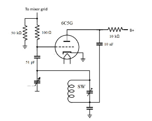
What is the type of this circuit and how to get it to oscillate on higher bands??
I hope to see your comments, thanks
Harri
To thank the Author because you find the post helpful or well done.
Oscillator problem with a Stewart Warner set
It looks like a variant of a Colpitts oscillator. Make sure that the 10 nF capacitor and the capacitor from the tank circuit to ground are in good order and of a type with good RF properties. If there have been paper capacitors originally and you need to recap the set, use polypropylene (MKP) capacitors, not polyester/mylar (MKT) in those positions. Also, make sure that the 6C5G is in good status and that the anode resistor has correct value.
To thank the Author because you find the post helpful or well done.
Oscillator problem with a Stewart Warner set
Also if heater voltage low or triode gain is low, the circuit will fail to oscillate at higher frequencies.
The 10nF from anode to coil is a potential divider with the capacitor at that point to ground for the feedback gain, so those two capacitors and the anode to HT 10 K Ohm resistor are critical.
Also check the 50 kΩ and maybe disconnect connection to mixer and see RF level at that point vs frequency.
It might be more like a Clapp oscillator than Colpits, but both use divider of two capacitors to set feedback gain. It's not a Hartley as it uses a tapped coil or transformer feedback. Probably it's Colpits as it's parallel tuned rather than series LC (Clapp).
To thank the Author because you find the post helpful or well done.