philips: 930A Philips - Hidden Reaction
? philips: 930A Philips - Hidden Reaction
This Philips 930A set has one of the most beautiful cases ever made, so I decided to take a closer look at the schematic.
The schematic is one of the simplest around with an input grid-leak detector, an audio preamp triode, and an output pentode. But the inductor load at the grid leak detector made me think that some regeneration (Rückkopplung) was designed in, simply by the presence of an inductive Plate load.
This use of regeneration would fall under the category of "trade secret", so there is no need to change the classification of this radio from "TRF without reaction" to "TRF with reaction". Philips probably wanted it that way.
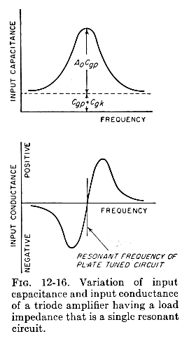
According to F. E. Terman's 1955 Electronic and Radio Engineering 4th edition page 427, when an inductive plate load is presented to a triode, the input conductance at the grid becomes negative below the frequency of resonance at the plate. Below resonance the impedance of the tank circuit is inductive.

This resonant frequency may be very high because the only capacitance at the plate is the self-capacitance of the load inductor and the Miller-multiplied grid-to-plate capacitance. In total, this should be under 30pF, if the inductor is not simply a high inductance choke (>1mH).
The photos that were posted under this radio did not clarify for me the value and the location of this inductor.
I wonder if an owner of this radio could tell the Forum what is the approximate value of the inductance, and what is it's position relative to the other inductances. If you own an inductance meter such as the Rhode&Schwarz BN6100, it would be great to know the the self-resonant frequency of this inductor too.
Another simple test could also show the effect of the inductor on gain: Shorting out the inductor with a short wire should lower the output volume. If using a foot-long aligator jumper, you should twist the wire tightly to avoid making a loop that might couple to the input coils.
Regards,
-Joe
To thank the Author because you find the post helpful or well done.
? I am not agree.

Lieber Joe.
Ich denke wir sind uns einig, dass auch ich was von Radios und Roehren verstehe.
Damit eine Drossel eine nennenswerte Spannung an der Anode erzeugen kann, die ausserdem bei jeder Frequenz variiert. Bedarf es einer hohen Induktivitaet. Deren Phasengang sehr flach sein muss, und daher eine niedrige Guete haben muss.
Was aber wieder einer hohen Spannung widerspricht.
Es ist also nicht so wie Du vermutest sagt mein Kopf.
Ich habe mir deshalb das Modell angesehen und konnte meine Idee als Wirklichkeit sehen.
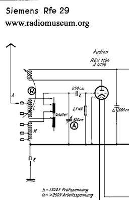
Diese Drossel ist eine Spule, drehbar als Variometer, im Innern der Kreisspule.
Sie arbeitet dort als manuelle Rueckkopplung
Dear Joe.
I thinks we are us agreed, that also I what knows about radios and tubes.
So that a RFC can produce an appreciable tension at the anode which in addition varies with every frequency. One needs a high inductance. Whose phase characteristic must be very flat, and have to have therefore a low kindness.
What, however, contradicts a high tension again.
It is not therefore so how you presume says my head.
I had a look at the model therefore and could see my idea as reality.
please see Attachments
This RFC is a reel, swivelling (rotating coil) as variometers, inside of the Tuning- Coil.
They works there as manualy Regeneration (positive feedback) see pic
.
O.K. ?
I hope, you can agree!
hans
- Bild 1 Philips (23 KB)
- Bild 2 Philips (14 KB)
- Bild aus RMorg. (38 KB)
To thank the Author because you find the post helpful or well done.
Tickler control
Dear Hans, thank you for clarifiying the nature of the coil in two languages.
So the plate coil is a classic regeneration tickler, with variometer style coil rotation for regeneration control.
The front knob on the lower left rotates the tickler coil.
In this case, the set description should be updated to indicate the use of "reaction"
By the way, I am accustomed to use the word "reaction", or "reactive" to imply a capacitive or inductive load which has a reactance=1/susceptance. I use "regeneration" or "regenerative" to imply positive feedback, or the effect of negative conductance/resistance.
I marked two of your your photos to show the location of the control shaft of the rotating tickler coil.
Your comments about the magnitude and constant 90o phase of the inductive load were useful for the next time I see an inductive plate load.
Regards,
-Joe
To thank the Author because you find the post helpful or well done.
