Putting in my valve radio a stereo decoder
? Putting in my valve radio a stereo decoder
A few years ago, I’ve tried to upgrade one of my great valve radios to be a full stereo device.
It was some kind of Grundig set, license produced in my country, with 11 valves, two separate channels with two output transformers with EL84-s.
I was thinking about possibility to make them a full stereo, putting inside a stereo decoder.
I have use a MC1310 chip, put whole construction in old screening IF transformer can, because chip is very small and don’t look so odd on chassis.
Thing works, but never give a good quality stereo sound.
A stereo indication lamp glows even on weaker stations, but sound is a little distorted, and stereo effect is poor.
My thoughts are that MC1310 isn’t so bad quality chip, like are my results in this project.
Probably something missing in this project, like signal level adjustment in and out of the decoder, some kind of output filtering etc. ; something what good quality sets have calculated in factory production.
Is anyone of you tried to do something like this, and what were the results?
Sorry I can’t write German, but I know read and understand them, so any comment is welcome.
Here is a schematic diagram, red lines shows like I’ve connect a decoder.
Best regards.
Attachments:- 604_Stereo_1 (167 KB)
To thank the Author because you find the post helpful or well done.
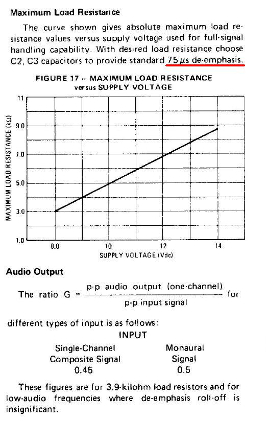
De-emphasis
You need to disconnect any de-emphasis, which is normally on the discrimator output or the 38KHz DSBSC L-R is too attenutated. In Europe you need to add an approximately 56KHz RDS trap and in USA RDS trap and 67KHz SCA traps.
But possibly the De-emphasis is at E and E' on the ECC83 anyway.
Make sure the MC1310 supply is decoupled with 1nF, 100nF and 100uF close to the IC ground and Supply pin and that the 3k3 pot is adjusted correctly. Check that the MC1310 input level is not too high, if they are then a pair of resistors as potential divider is needed. You may need a unity gain FET buffer (Source follower) as the coupling capacitors suggest high impedance. The ECC83 is about 600K to 1.3M Ohm depending on volume control. The MC1310 may be 10K to 20K input impedance (suggested by 2.2uF input decoupling)
There is nothing wrong with an MC1310.
To thank the Author because you find the post helpful or well done.
de-emphasis
Thanks for reply mr. Watterson.
I’ve forgot to mention that I was remove de-emphasis (47K resistor / 1nF capacitor), and MPX signal for chip input is taken like red line is onto diagram shown.
Attachments:- emphasis (92 KB)
To thank the Author because you find the post helpful or well done.
Impedance
Probably the MC1310 input impedance is too low (add FET buffer). Also check what level there is with MC1310 disconnected with a 680k "dummy" load instead. See how that level compares with MC1310 data sheet as too much signal will distort.
To thank the Author because you find the post helpful or well done.
input
I have noticed that’s chip input level can be the main culprit for bad results, in collaboration with impedance mismatch (valve to chip).
What you suggest for lowering input level? I am concerned to put something here because of possible phase shift.
Can you outline some concrete proposal please?
I would be very grateful for a sketch, which includes all detected troubles (input level lowering – impedance mismatch- and 56kHz trap).
Thanks in advance.
To thank the Author because you find the post helpful or well done.
pot
A series resistor and then 22k to ground.
But you need to know. Or else put a 500K pot
To thank the Author because you find the post helpful or well done.
pot
If I understand, you suggest something like that
Attachments:- decoder_1310 (117 KB)
To thank the Author because you find the post helpful or well done.
construction
And here you can see finished decoder.
Whole construction is fitted into old IF-screening can.
There were two holes on top, one is for crocodile clamp for frequency meter, and other for adjustment trimmer.
Attachments:To thank the Author because you find the post helpful or well done.
divider
Mr. Watterson, thanks for your suggestion.
I’ve added a pair of resistors as potential divider, and the result was significantly sound improvement.
At first I’ve got boosted high frequencies on speakers, not so prominent bass, and mid frequency range almost nothing.
It seems that there is no single recipe for this project, and whole story isn’t as easy as I thought.
But now it sounds better than it was at the beginning.
Thanks for suggestions.
Best regards.
To thank the Author because you find the post helpful or well done.
Measurements and data sheets
IC and Transistor radio circuits are usually low impedance, 10K to 100K ohms.
Valve (Tube) circuits are typically 600k ohms to 5M Ohms impedance.
Signal levels are also quite different. So to do it properly you must first know the source impedance the MC1310 input is designed for, or at least what the input impedance is. It could be 10K to 50K. I don't know, you need to consult its datasheet. We can see the existing discriminator is loaded by no less than 300K Ohms as it drives a pair of volume controls and then via decoupling capacitors to 1M Ohm "grid" resistors.
So one interface would be a 2N3819 FET with a 470K gate to ground resistor, fed from the Discriminator 22nF decoupling resistor, drain to the MC1310 supply and then a 22K or 47K Ohm pot as the source to ground resistor, that drives the 2.2uF on the MC1310 input. That would give a maximum gain of 1 and impedance matching. Ideally you would measure the discriminator output level, assume the FET is a gain of one and then have a pair of fixed resistors in series as a potential divider / fixed attenuator that have a sum value of about 47K, and reduce the signal to the level required by the MC1310 datasheet. If needed you can even boost the 38KHz L-R level a little by a capacitor with series resistor in parallel with the "upper" resistor of the potential divider/attenuator on the FET source pin to ground.
To thank the Author because you find the post helpful or well done.
Alignment
Also the Tuning in a station, IF alignment and Discriminator adjustment are all more critical for Stereo as you need about 56 KHz bandwidth instead of 15kHz for mono at the output of the discriminator. I don't remember what IF bandwidth you need, but if it's too narrow then mono still sounds OK but stereo would be poor.
To thank the Author because you find the post helpful or well done.
buffer
Thanks mr.Watterson
I made a sketch of your suggestions, please take a look and warn me if something I did not understand.
I will try out and I’ll report the results.
Attachments:- decoder_1310_add (115 KB)
To thank the Author because you find the post helpful or well done.
Nearly correct
The two "ends" of the pot are between the 0V and FET source and the "wiper"/"slider" (usually middle contact) goes to the MC1310.
Otherwise it's correct.
To thank the Author because you find the post helpful or well done.
cerrection
Diagram is corrected in the way you said.
MC1310 data :
-Wide Dynamic Range: 0.5 to 2.8V(p–p) Composite Input Signal
-Wide Supply Range: 8V to 14V
-Input impedance at pin2 : min 20 - max 50 (Kohm)
Attachments:- decoder_1310_add2 (113 KB)
To thank the Author because you find the post helpful or well done.
Try it!
Well, we don't know what the level from the Ratio Discriminator is.
Adjusting without an Audio signal Meter:
- Start with pot at minimum, and turn up till stereo pilot lights. Note position
- Turn up till it sounds distorted. Note position.
- Turn pot back and see what it's like between half way of two noted positions and 2/3rds of way toward higher position
But actually measuring level at input of MC1310 and setting pot would be best. Make sure radio is "perfectly" tuned in as this affects stereo more than mono.
2.8V pk to pk is 1V RMS on an RMS voltmeter.
To thank the Author because you find the post helpful or well done.
no success
I’ve tried this and there’s no significant sound improvement.
Didn’t have 2N3819 FET, I’ve use a BF245.
I have noticed that stereo lamp do not glows when magic eye has full deflection; instead that-stereo lamp sprang to live when station is tuned “a little aside”.
I will try to realign the discriminator.
To thank the Author because you find the post helpful or well done.
At finally
Just to inform, I’ve managed to solve the trouble.
After many spent hours trying to realign and change IF coupling, stereo sprang to live.
It was really pity to dismantle IF transformers and change distance between coils.
But when started I’ve couldn’t back.
It was hard to find best position between coils, to find acceptable loss of selectivity.
When you move coils too close to each other, this produce whistling.
Anyway, it is possible to achieve this, the key thing is to adjust the impedance like mr.Watterson suggest.
But whole sort of other troubles will appear, like boosted high frequencies.
This was probably because original de-emphasis must be removed if you do this.
And after stereo decoder probably must follow some kind of filtering that clear any residue of 19 kHz pilot tone.
Mr.Watterson many thanks for your suggestions.
To thank the Author because you find the post helpful or well done.
De-emphasis
I hope that I do not boring the audience,
I’ve forgot to mention an important thing.
According to MC1310 datasheet, applying different load resistors (from Vcc to pin 4 and 5),
you can affected to gain, so that the chip can be adapted to various operating output levels.
Figures shown in datasheet are intended to provide a 75uS (microseconds) deemphasis, and this is for USA broadcasting standard.
When you choose load resistors for your application, you must choose C2 and C3 to provide a 50uS deemphasis- European standard.
I didn’t know this on startup, so I got unpleasant sound; sounds like treble is too much added, high frequencies are too boosted. In the same time bass sounds like “tumbling”.
I know- describing sound quality is a very subjective feeling, but overall acoustic impression: thumb sound with screaming treble.
Must admit that I don’t understand deemphasis function in this case.
I have never seen deemphasis going from B+ to the channel outputs, in most cases deemphasis is a simple low pass filter going to the ground (-).
I don’t have knowledge to calculate values of the C2 and C3 to get proper 50uS time constant for this case (I’m just hobbyist), so I was study various diagrams using the same chip, and found that European sets often used combination 5,6k/6,8nF or 4,7k/15nF.
Both of combinations give better sound results then 3,9k/20nF from chip datasheet intended to provide 75uS time constant.
If anyone else comes to such a crazy idea like I did, seems that matching time constant is the important thing, together with impedance matching like mr.Watterson in previous post warned.

To thank the Author because you find the post helpful or well done.