VM Tubes: 1 - Heil Tubes
VM Tubes: 1 - Heil Tubes

Heil Tubes
In 1935 both Oskar Heil, a German engineer, and his wife, Agnessa Arsenjeva, coming from the Department of Physics at the Leningrad Polytechnic Institute, published the first article describing their idea on how electrons could be bunched by velocity modulation. Later Mrs. Heil returned to Russia, while O. Heil started an intense work at the British STC that developed a line of oscillators based upon the same operating principle.

Fig. 1 – (a) equivalent circuit of Heil tube; (b) section of the tube; (c) potential distribution through electrodes. From original drafts of the early devised structure.
A section of the Heil tube and its equivalent circuit are given in figs. 1(b) and 1(a). A is the cathode, the electron beam being indicated as arrow terminated dotted line; B and D are focusing grids; C is the drift electrode or resonator, coupled to the resonating cavity here represented as lumped L’C’ circuit. Fig. 1(c) shows how instantaneous potential of the drift electrode C varies (dotted segments), following the oscillations in the high-Q resonator. Electrons are first accelerated by the uniform field from cathode A to the grid B, gaining a constant velocity. Then, in the region from grid B to the resonator C, electrons are alternately more or less accelerated by the oscillating potential on C itself, so that bunching occurs. Bunched electrons interfere with the drift electrode releasing energy and sustaining oscillations in the cavity.

Fig. 2 - Here are cross-section and mounting drawings of an actual Heil tube, the STC V233A/1K. The electrode structure has been slightly modified, adding a screen grid and replacing the second focusing grid, D in Fig. 1, directly with the anode. A powerful magnet is required to keep the electron beam focused inside the resonator. The resonator is biased by a DC voltage, typically between 150 and 400V, the actual value depending upon the operating frequency, from 2700 to 4200MHz.
Heil tubes could be AM modulated applying modulation signal either to G1 or to the screen grid. FM modulation was also possible, applying the signal to the resonator. Efficiency was poor, in the order of 10 % and probably this was the reason why Heil tubes became soon outdated in favor of the most versatile klystrons.
STC produced some Heil tubes both for military applications and for microwave communication relays. Unfortunately, apart from some data sheets, I found very little information about these tubes, their applications and possible developments of dual port amplifying structures. But there is another open question. O. Heil worked at STC in the late ‘930s. At the outbreak of the war he returned to Germany and after the war he moved to the States. But I did not find any trace of similar tubes developed in Germany or in US, while apparently the sole STC continued the development and production for communication relays through the fifties. And what about the work of Mrs. Heil once back in Russia?
In the tube section I found 15 entries. Of course for some tubes, also the equivalent service type CVxxx is coded. I do not know if more similar devices are present under different codes.
V190C/1M
V230A/1K
V233A/1K
V235A/1K
V237C/1K
V239C/1K
V240C/1K
V240C/2K
V241C/1K
V245C/1K
V246/1K
V246A/1K
V246A/2K
V247C/1K
V249C/1K
V271C/3M

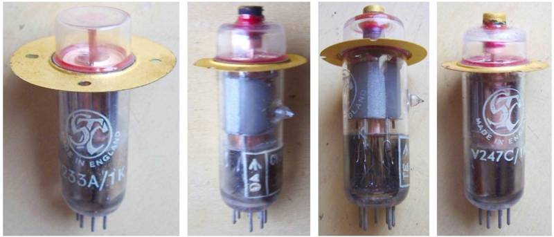
Fig. 3 – From left: V233A/1K, V239C/1K, V241C/1K, V247C/1K
Any further information will be appreciated.
To thank the Author because you find the post helpful or well done.
WWII German Production

It could be expected indeed and actually Heil tubes built in Germany around WWII, when Oskar Heil moved to this Country, are coming out. Thanks to the precious information received from Otmar Jung, I found that Lorenz built some oscillators covering wavelengths from 23 to 10 cm, about 1.3 to 3.0 GHz. Unfortunately the documentation is in German and it is not clear for me if it just talks of laboratory prototypes.
Otmar also gave me the code of one Heil tube actually produced, the Lorenz RD12La operating from 20 to 25 cm. It was already coded in Radiomuseum as reflex klystron.
I also found an early British service type CV39, corresponding to the STC S22AF model. This last code is quite different from other known codes assigned to Heil devices by the same manufacturer, all beginning by Vxxx. Maybe that more types could have been made.
I hope that some members could complete the overview of this very early VM tube type.
To thank the Author because you find the post helpful or well done.