SuperCAVIAR Converter 260-28
Albis, Albiswerke AG (Siemens Switzerland AG / Telefunken Zürich AG / Siemens-Albis); Albisrieden
- Country
- Switzerland
- Manufacturer / Brand
- Albis, Albiswerke AG (Siemens Switzerland AG / Telefunken Zürich AG / Siemens-Albis); Albisrieden
- Year
- 1981–1985
- Category
- Signal Processing and Computing
- Radiomuseum.org ID
- 357791
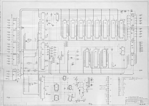
Click on the schematic thumbnail to request the schematic as a free document.
- Number of Transistors
- 1
- Semiconductors
- MC8T26 DM81LS96 SN74S00 SN74S04 SN74LS00 SN74LS02 SN74LS04 SN74S08 SN74S10 SN74S11 SN74S30 SN74S133 SN74S138 SN74LS174 SN74LS193 SN74LS293 SN75158 MC6821 MC68A54 µA9637 TBP28L22 MBM2764 MBM27128 2N3704 1N914 ZD6,2
- Wave bands
- - without
- Power type and voltage
- Powered by external power supply or a main unit. / DC 5 Volt
- Loudspeaker
- - - No sound reproduction output.
- Material
- Printed Circuit Board
- from Radiomuseum.org
- Model: SuperCAVIAR Converter 260-28 - Albis, Albiswerke AG Siemens
- Shape
- Chassis only or for «building in»
- Dimensions (WHD)
- 248 x 152 x 10 mm / 9.8 x 6 x 0.4 inch
- Notes
-
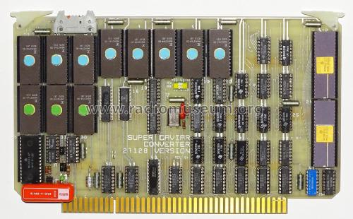
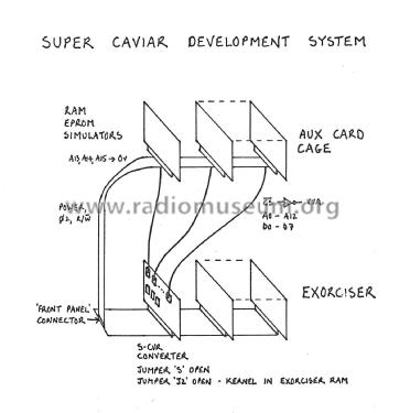
The 260-28 SuperCAVIAR Converter was designed to upgrade standard CAVIAR Microcomputers by expanding the 64 Kbyte addressing limit of the 6800 microprocessor to a physical address space of 512 Kbytes. The Converter provides independent firmware and RAM maps, dynamic allocation of common RAM, automatic inter-page transfer modes, and a RAM/EPROM overlay. 152 Kbytes of EPROM are incorporated on the card to store the interpreter and libraries, which are compactly written in assembly language. The expanded firmware includes new data types, a context editor, an enhanced debug monitor with trace facility, a memory-based file system, and extended data communications, histogramming, array-handling and graphics routines, including isoline plotting, line-fitting and fast Fourier transform and inverse transform operations.
The first address space is a fixed 24 Kbyte area which is unmapped. In this area reside an enlarged kernel of the interpreter, a debug monitor and RAM stack, the floating-point arithmetic and function processor (APU), and interfaces for CAMAC, GPIB, FSK cassette, video alphanumerics and data communications I/O.
The second address space, consisting of 128 Kbytes of EPROM, comprises library firmware which is mapped into one 8 Kbyte logical area. The process of firmware mapping is transparent to the user, who simply finds that there is a greater number of interpreter calls at his disposition.
The third address space, which can accommodate a special 256 Kbyte RAM card, or a mix of RAM and user-program EPROM, is mapped into 32 Kbytes. Programs and data can be readily interchanged between different RAM maps, and programs resident in more than one map can be executed with no limit to the jumps between maps. RAM maps are also assigned logical unit numbers, and can be referenced as sequential files by I/O instructions.
All the memory mapping functions of the Converter are controlled by two peripheral interface adaptors (PIAs) located at addresses 4-7/8-B, immediately following the graphics generator. These locations were chosen to permit access by direct mode addressing for the highest speed of map switching, but they superpose base page RAM. So the PIAs are configured as write-only, and current map numbers are read back from RAM. Schottky TTL is used for the address translation logic, as a result of which mapped memory accesses can be achieved without extending the microprocessor cycle time.
SuperCAVIAR interrupts are vectored through locations in firmware immediately below FFFF, which are unmapped, and then through locations in low-order RAM. The common RAM at the base of each map is also used for the EPROM and RAM pointers required for inter-RAM communication, and for the storage of common parameters.
The Converter also includes an Advanced Data Link Controller (ADLC), digital PLL clock circuit and interrupt-driven software package that can be used to control multiple external readout processors in large data acquisition systems. The transmission range exceeds 1 km over telephone-type line. Up to 256 SuperCAVIARS can be connected in an ADLC loop, and data can be exchanged between that acting as primary station and any addressed secondary (or all secondaries simultaneously). Any secondary can be commanded to treat the ADLC loop as terminal I/O. Thus the primary SuperCAVIAR can (either by program execution or from its terminal) load and run programs in any of the secondaries. Circuit integrity is maintained by a reed relay should any SuperCAVIAR in the ADLC loop be powered down.
The SuperCAVIAR Converter was designed by Bruce Taylor and manufactured by Siemens-Albis SA from 1981 to 1985.
- Net weight (2.2 lb = 1 kg)
- 0.3 kg / 0 lb 10.6 oz (0.661 lb)
- Mentioned in
- -- Original-techn. papers. (Conference Paper May 1981)
- Literature/Schematics (1)
- -- Schematic
- Author
- Model page created by Bruce Taylor. See "Data change" for further contributors.
- Other Models
-
Here you find 176 models, 152 with images and 146 with schematics for wireless sets etc. In French: TSF for Télégraphie sans fil.
All listed radios etc. from Albis, Albiswerke AG (Siemens Switzerland AG / Telefunken Zürich AG / Siemens-Albis); Albisrieden
Collections
The model SuperCAVIAR Converter is part of the collections of the following members.
