- Country
- France
- Manufacturer / Brand
- AOIP, AOP (A.O.I.P., A.O.P.), Association des Ouvriers en Instruments de Précision; Paris
- Year
- 1964 ??
- Category
- Service- or Lab Equipment
- Radiomuseum.org ID
- 338357
Click on the schematic thumbnail to request the schematic as a free document.
- Wave bands
- - without
- Power type and voltage
- Alternating Current supply (AC)
- Loudspeaker
- - - No sound reproduction output.
- Material
- Metal case
- from Radiomuseum.org
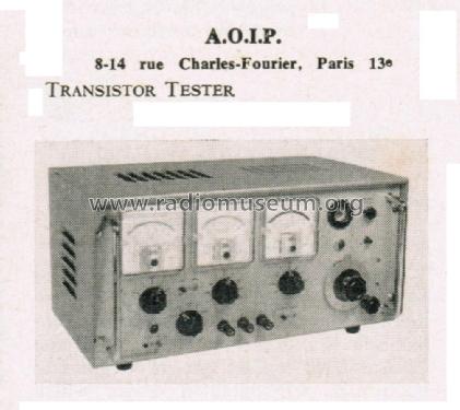
- Model: Transistor Tester - AOIP, AOP A.O.I.P., A.O.P.,
- Shape
- Tablemodel, with any shape - general.
- Notes
-
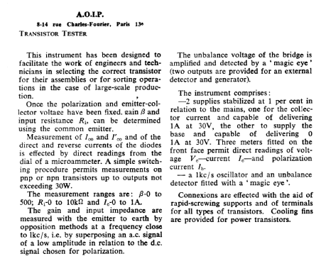
This instrument has been designed to facilitate the work of engineers and technicians in selecting the correct transistor for their assemblies.
Fixing the polarization and emitter-collector voltage, we can determinate gain β and input resistance Ri.
Direct and reverse current of the diodes is read directly from the dial of a microammeter.
The measurement ranges are: β 0 to 500; Ri 0 to 10 kΩ and Ic 0 to 1A.The instrument comprises: Two supplies stabilized at 1 per cent in relation to the mains, one for the collector that gives 1 A at 30 V, the other to supply the base that gives 0.1 A at 30 V.
Three meters that permits direct readings of voltage Vc - current Ic and polarization current Ib.All many other characteristics are in the original attached article.
- Mentioned in
- From “Electronic Engineering”, volume 34, year 1964, February.
- Author
- Model page created by Pier Antonio Aluffi. See "Data change" for further contributors.
- Other Models
-
Here you find 30 models, 29 with images and 10 with schematics for wireless sets etc. In French: TSF for Télégraphie sans fil.
All listed radios etc. from AOIP, AOP (A.O.I.P., A.O.P.), Association des Ouvriers en Instruments de Précision; Paris