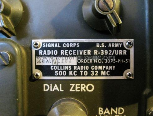
R-392/URR
Collins Radio Company; Cedar Rapids (IA)
- Produttore / Marca
- Collins Radio Company; Cedar Rapids (IA)
- Anno
- 1951–1962
- Categoria
- Ricevitore professionale (può includere bande amatoriali)
- Radiomuseum.org ID
- 72005


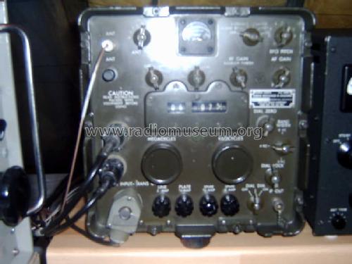
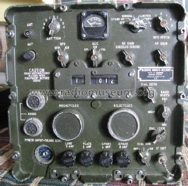
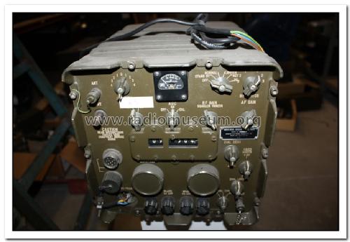
Front View of my Radio
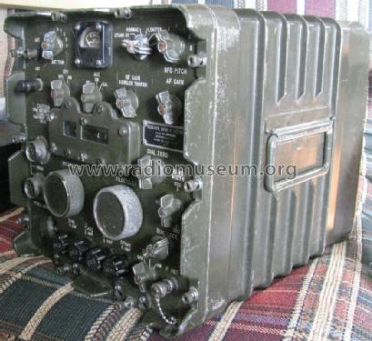
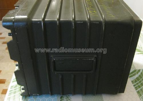
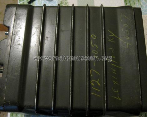
Side V=view of my radio
zeitschrift Funk 3/83
Zeitschrift Funk 3/83
Like a Collins
Dettaglio ritocco verniciatura
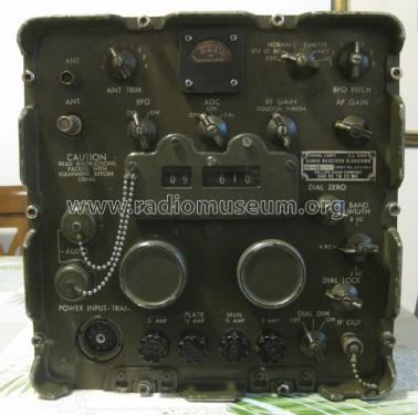
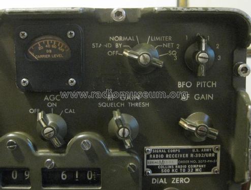
Vista frontale
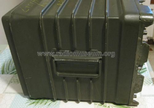
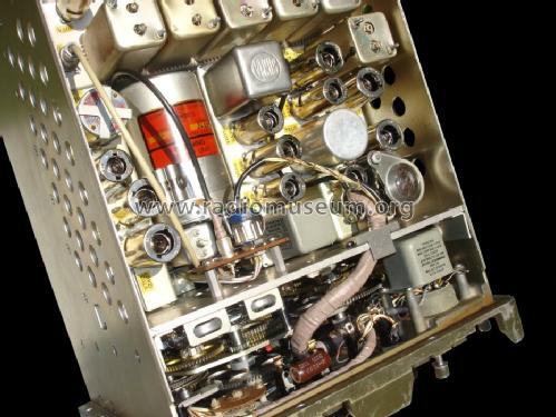
Lato sinistro
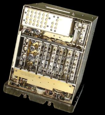
Lato destro
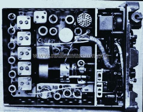
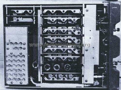
Parte superiore
Clicca sulla miniatura dello schema per richiederlo come documento gratuito.
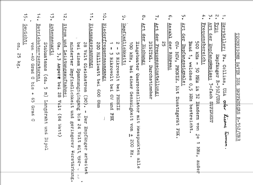
- Numero di tubi
- 25
- Valvole
- 26A6 26A6 26C6 26C6 6AJ5 6AJ5 26A6 26A6 26A6 26A6 26A6 26A6 12AU7 12AU7 12AU7 26A6 6AJ5 6AJ5 6AJ5 26A7GT 26A6 12AU7 26A6 12AU7 26D6
- Principio generale
- Supereterodina a doppia / tripla conversione
- Gamme d'onda
- Onde medie (OM) e più di 2 gamme di onde corte (> 2 x OC).
- Tensioni di funzionamento
- Batterie (di accumulatori e/o a secco) / 24-28 Volt
- Altoparlante
- - Per cuffie o amplificatori esterni
- Potenza d'uscita
- 0.2 W (qualità ignota)
- Materiali
- Mobile di metallo
- Radiomuseum.org
- Modello: R-392/URR - Collins Radio Company; Cedar
- Forma
- Soprammobile con qualsiasi forma (non saputo).
- Dimensioni (LxAxP)
- 295 x 295 x 360 mm / 11.6 x 11.6 x 14.2 inch
- Annotazioni
-
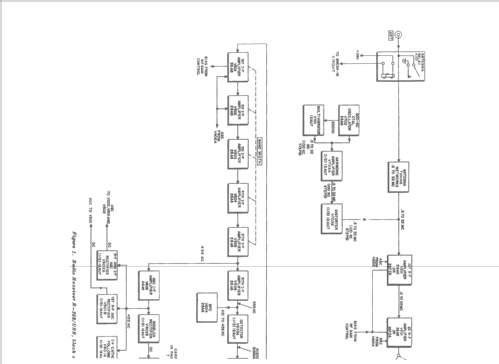
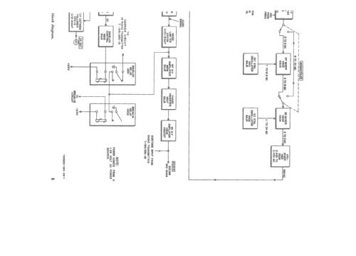
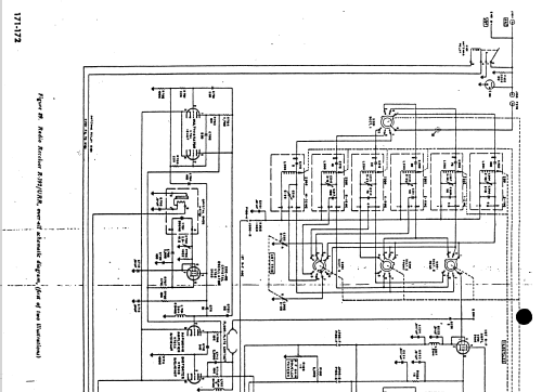
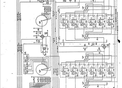
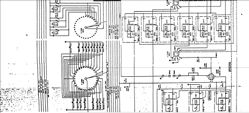
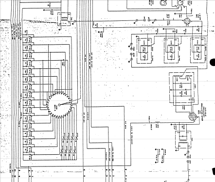
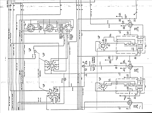
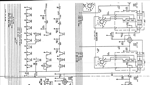
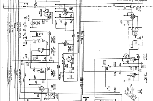
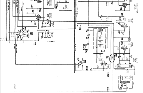
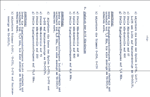
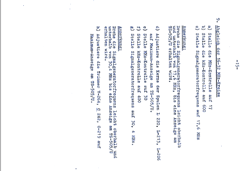
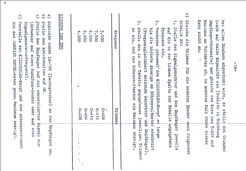
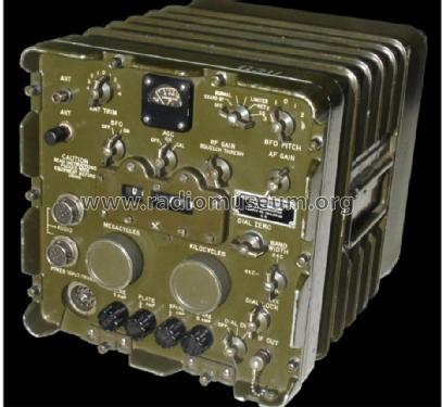
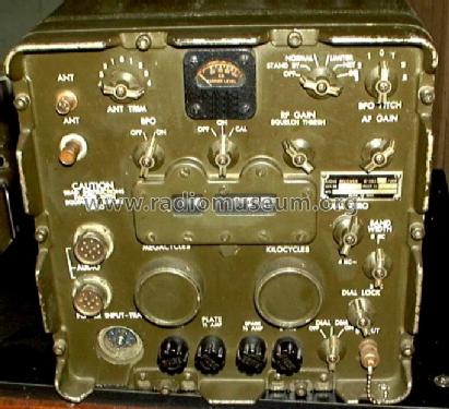
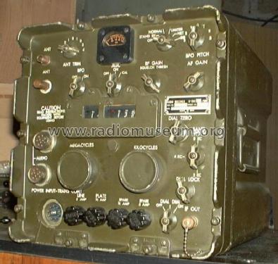
Collins R-392/URR radio receiver: coverage 0.5 to 32 MHz in 32 bands, CW (A1)/ MCW (A2)/ AM (A3)/ FSK (F1) with a matching converter.
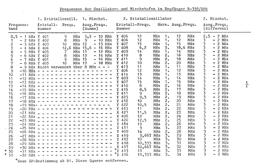
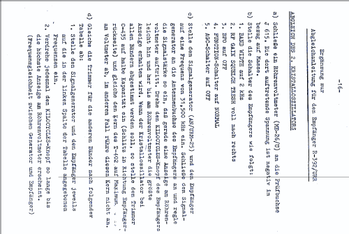
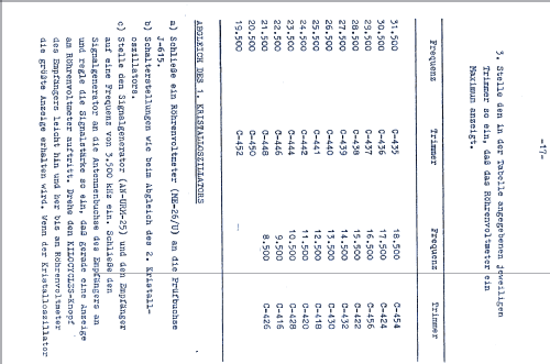
Triple conversion below 8 MHz (IF 9.5-18 MHz / 2-3 MHz / 455 kHz), double conversion above (IF 2-3 MHz and 455 kHz). 2 RF stages + 6 IF stages. Three selectable IF-bandwidths (8 / 4 / 2 kHz), AGC, 100 KHz crystal-calibrator. PTO-VFO. Frequency readout provided by 5 digits mechanical counter. All connections on the front panel.
Also made by other manufacturers.
Low supply tubes used, partly 26A6 has been replaced 26FZ6. Tube spares case CY-1298/URR.
Used as a part of AN/GRC-19 vehicular system, matching transmitter T-195, or also as standalone FSK radioteletype receiver system.
- Peso netto
- 23.7 kg / 52 lb 3.2 oz (52.203 lb)
- Fonte dei dati
- -- Original-techn. papers.
- Bibliografia
- Shortwave Receivers - Past & Present (3rd ed.)
- Letteratura / Schemi (1)
- Communications Receivers
- Autore
- Modello inviato da Alexander Küffer. Utilizzare "Proponi modifica" per inviare ulteriori dati.
- Altri modelli
-
In questo link sono elencati 100 modelli, di cui 77 con immagini e 35 con schemi.
Elenco delle radio e altri apparecchi della Collins Radio Company; Cedar Rapids (IA)
Collezioni
Il modello fa parte delle collezioni dei seguenti membri.
Discussioni nel forum su questo modello: Collins Radio: R-392/URR
Argomenti: 2 | Articoli: 2
Allego il foglio di collaudo del ricevitore, con le misure di sensibilità in uV per un SINAD di 10 dB. Data: 5 giugno 1969.

Allegati
- Receiver Test Data Sheet (230 KB)
Tonino Giagnacovo, 03.Jan.16
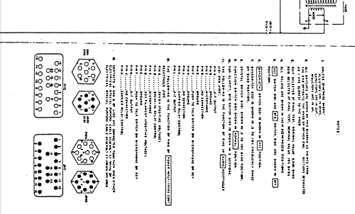
From the original instruction book, here the tube layout informations necessary for troubleshooting this receiver:
| V201 | 26A6 | 1st R-F Amplifier RF |
| V202 | 26A6 | 2nd R-F Amplifier RF |
| V203 | 26C6 | 1st Mixer RF |
| V204 | 26C6 | 2nd Mixer RF |
| V401 | 6AJ5 | 1st Crystal Oscillator CRY |
| V402 | 6AJ5 | 2nd Crystal Oscillator CRY |
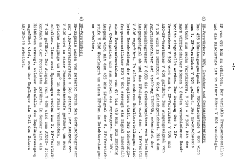
| V501 | 26A6 | 1st I-F Amplifier I-F |
| V502 | 26A6 | 2nd I-F Amplifier I-F |
| V503 | 26A6 | 3rd I-F Amplifier I-F |
| V504 | 26A6 | 4th I-F Amplifier I-F |
| V505 | 26A6 | 5th I-F Amplifier I-F |
| V506 | 26A6 | 6th I-F Amplifier I-F |
| V601A/B | 12AU7 | I-F Cathode Follower / 1st R-F AGC Rectifier A-F |
| V602A/B | 12AU7 | R-F and I-F AGC Rectifier A-F |
| V603 | 12AU7 | Detector / Noise Limiter A-F |
| V604 | 26A6 | BFO A-F |
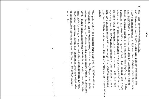
| V605 | 6AJ5 | Squelch Control A-F |
| V606 | 6AJ5 | 1st A-F Amplifier A-F |
| V607 | 6AJ5 | Phase Inverter A-F |
| V608 | 26A7GT | 2nd A-F Amplifier A-F |
| V609 | 26A6 | AGC I-F Amplifier A-F |
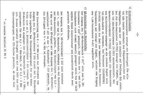
| V701 | 12AU7 | Multivibrator CAL |
| V702 | 26A6 | 200 kHz Crystal Oscillator CAL |
| V703A/B | 12AU7 | Harmonic Amplifier / Distorter CAL |
| V801 | 26D6 | VFO - Mixer VFO |
I-F: located on IF-Subchassis
A-F: located on A-F Subchassis
VFO: located on VFO - Mixer - Subchassis
CAL: located onCalibrator - Oscillator Subchassis
CRY: located on Crystal Oscillator Subchassis
RF: located on R-F Subchassis
Martin Bösch, 09.May.10