- Pays
- Etats-Unis
- Fabricant / Marque
- DuMont Labs, Allen B., Inc.
- Année
- 1956
- Catégorie
- Radio - ou tuner d'après la guerre 1939-45
- Radiomuseum.org ID
- 82578
-
- alternative name: Dumont Television & Radio


Sams Photofact Folders
Cliquez sur la vignette du schéma pour le demander en tant que document gratuit.
- No. de tubes
- 5
- Principe général
- Super hétérodyne (en général); FI/IF 455 kHz; 2 Etage(s) BF
- Circuits accordés
- 6 Circuits MA (AM)
- Gammes d'ondes
- PO uniquement
- Tension / type courant
- Alimentation Courant Alternatif (CA) / 110 - 120 Volt
- Haut-parleur
- HP dynamique à aimant permanent + bobine mobile / Ø 4 inch = 10.2 cm
- Matière
- Plastique moderne (pas de bakélite, ni de catalin)
- De Radiomuseum.org
- Modèle: 1120 - DuMont Labs, Allen B., Inc.
- Forme
- Modèle de table sans poussoirs, modèle cheminée
- Remarques
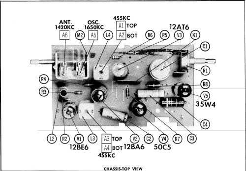
- The Dumont Model 1120 is an AC Operated 5 Tube AM Receiver.
- Source du schéma
- Beitman Radio Diagrams Vol. 17, 1957
- Schémathèque (1)
- Photofact Folder, Howard W. SAMS (Date 4-57, Set 354, Folder 4)
- Auteur
- Modèle crée par Egon Penker. Voir les propositions de modification pour les contributeurs supplémentaires.
- D'autres Modèles
-
Vous pourrez trouver sous ce lien 307 modèles d'appareils, 159 avec des images et 250 avec des schémas.
Tous les appareils de DuMont Labs, Allen B., Inc.
Contributions du forum pour ce modèle: DuMont Labs, Allen B: 1120
Discussions: 2 | Publications: 6
I'm preparing to restore the circuit of a Dumont 1120. I noticed that the measured resistances for couplet were far off. The 470K resistor between pin 5 and pin7 measured 1.8M ohms. The other 470K resistor between pin 6 and pin 4 measured 5.5M ohms. And the 10Meg resistor between Pin 1 and Pin4 measured 16.5M ohms.
Is it common for these to fail? I just had to rebuild one on a Sylvania R518 couplet.

Schematic included by DR
Pièces jointes
- Couplet (49 KB)
Jay Graven, 01.Oct.21

 Restoring a Dumont 1120 clock radio. Unfortunately all four screw posts have broken away from the cabinet. I still have the broken posts attached to the screws. Anyone know a good way to reglue the broken posts back to the cabinet? Will JB Weld work??
Jay Graven, 27.Sep.21