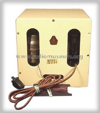
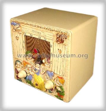
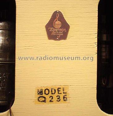
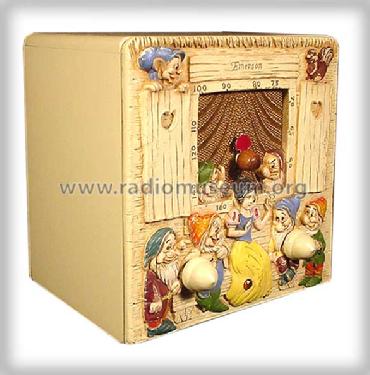
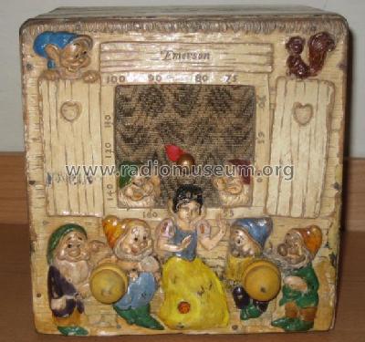
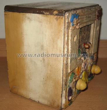
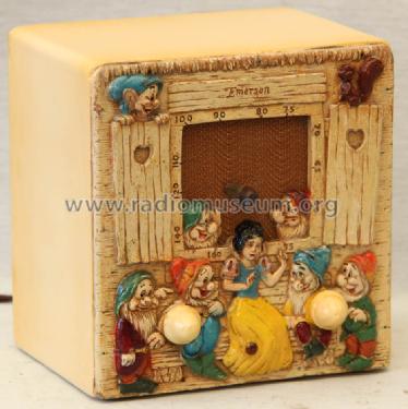
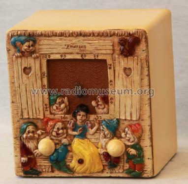
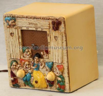
Q236 "Snow White"
Emerson Radio & Phonograph Corp.; New York, NY
- Produttore / Marca
- Emerson Radio & Phonograph Corp.; New York, NY
- Anno
- 1937
- Categoria
- Radio (o sintonizzatore del dopoguerra WW2)
- Radiomuseum.org ID
- 115976
-
- alternative name: Emerson Television

Ebay Nr. 220091255079 Bild bearbeitet.
Ebay Nr. 220091255079 Bild bearbeitet.
Ebay Nr. 220091255079 Bild bearbeitet.
Ebay Nr. 220091255079 Bild bearbeitet.
Ebay Nr. 220091255079 Bild bearbeitet.
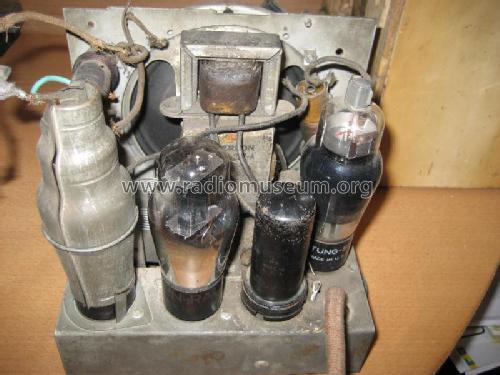
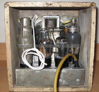
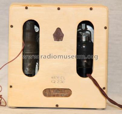
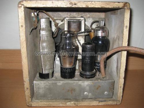
- Numero di tubi
- 4
- Principio generale
- A reazione (con rigenerazione)
- N. di circuiti accordati
- 2 Circuiti Mod. Amp. (AM)
- Gamme d'onda
- Solo onde medie (OM).
- Tensioni di funzionamento
- Alimentazione a corrente alternata (CA) / 115 Volt
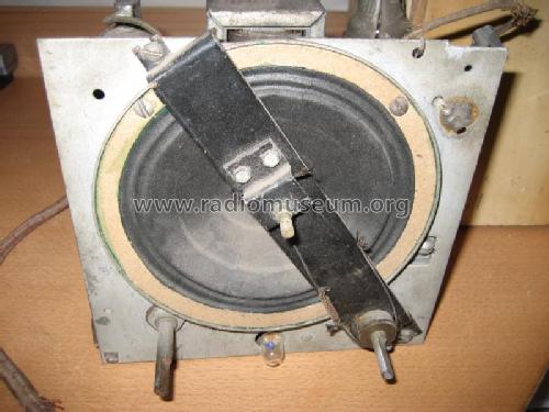
- Altoparlante
- AP elettrodinamico (bobina mobile e bobina di eccitazione/di campo) / Ø 5 inch = 12.7 cm
- Materiali
- Mobile in legno
- Radiomuseum.org
- Modello: Q236 "Snow White" - Emerson Radio & Phonograph
- Forma
- Radio di design, novelty, gadget, pubblicitaria o di forma inusuale
- Dimensioni (LxAxP)
- 185 x 185 x 145 mm / 7.3 x 7.3 x 5.7 inch
- Annotazioni
- Snow White & 7 Dwarfs in pressed wood. Hand painted.
- Fonte dei dati
- Collector's Guide to Antique Radios (6th edition)
- Bibliografia
- Table Top Radios Vol. 1 Stein 98
- Autore
- Modello inviato da Götz Linss † 27.06.21. Utilizzare "Proponi modifica" per inviare ulteriori dati.
- Altri modelli
-
In questo link sono elencati 2101 modelli, di cui 1158 con immagini e 1659 con schemi.
Elenco delle radio e altri apparecchi della Emerson Radio & Phonograph Corp.; New York, NY
Collezioni
Il modello Q236 "Snow White" fa parte delle collezioni dei seguenti membri.
Discussioni nel forum su questo modello: Emerson Radio &: Q236 "Snow White"
Argomenti: 2 | Articoli: 3
Hi Mark.....The component is a 3-5 watt resistor. It is very common for radio's of that era ( EARLY 30'S) The only troubles you might find with these are shorts to chassis. Just make sure it is grounded only where schematic has it so. Nice radio....I have done a couple, and never seemed to get them working too well. But it is a very sort after radio..............AL
Alfred Pugliese, 31.Dec.08
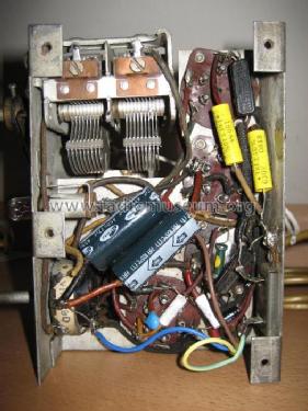
I'm in the process of restoring a Q-236 Emerson radio however whilst trying to piece together the schematic, I have got stuck at the heater circuit.
Let me explain, the set was originally made for the US market so 105-125VAC. The example I have got was for the South American market and I am told this was 230VAC. The resistive mains lead has been cut off so I have only three wire tails left to work from. One goes to the 25Z5 to make the HT but another feeds the heater circuit which must have had the built in resistance in the lead. Also in the circuit is this odd component which is made by Clarostat and measures about 8 ohms. See photo.
I found a schematic for a Q157 which appears very similar (same tubes etc) but this odd component is not included. Was this added for the Southern markets or is this a normal feature of these sets?
Since I submitted this, I have now solved the problem. The part in question is actually a 400R resistor which is a shunt for the dial bulb. When initially measured, the bulb was still in place and hence the 8R.
Thanks for looking anyway.
Allegati
- Component (42 KB)
Mark Andrews, 10.Dec.08