910 Stereo
Emud, Ernst Mästling; Ulm
- Country
- Germany
- Manufacturer / Brand
- Emud, Ernst Mästling; Ulm
- Year
- 1959 ?
- Category
- Broadcast Receiver - or past WW2 Tuner
- Radiomuseum.org ID
- 116943
Click on the schematic thumbnail to request the schematic as a free document.
- Number of Tubes
- 10
- Main principle
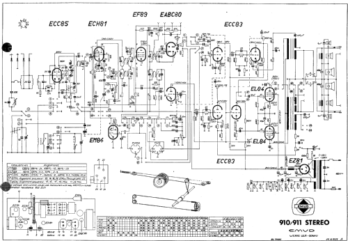
- Superheterodyne (common); ZF/IF 460/10700 kHz
- Wave bands
- Broadcast, Short Wave plus FM or UHF.
- Power type and voltage
- Alternating Current supply (AC) / 110 Volt
- Loudspeaker
- 6 Loudspeakers
- from Radiomuseum.org
- Model: 910 Stereo - Emud, Ernst Mästling; Ulm
- Notes
- Mono Radio mit Gegentakt-Endstufe, umschaltbar auf Stereo-NF-Verstärker mit jeweils einer EL84 pro Kanal.
- Literature/Schematics (1)
- -- Original-techn. papers.
- Author
- Model page created by Pius Steiner. See "Data change" for further contributors.
- Other Models
-
Here you find 422 models, 328 with images and 231 with schematics for wireless sets etc. In French: TSF for Télégraphie sans fil.
All listed radios etc. from Emud, Ernst Mästling; Ulm
Forum contributions about this model: Emud, Ernst Mästling: 910 Stereo
Threads: 2 | Posts: 7
Gregg Ruecker, 24.Jan.15
Greetings,
I am a new member with Radiomuseum and I live in the United States. I am a Ham operator and tube hobbyist. I have restored many amps and tuners form the US. I have just recently started to work on a beautiful Emud console stereo, model #910. I have the schematic and I have this question. The way the schematic is shown is a bit different from what I am used to here in the US. Can anyone help me understand the Europeon schematics. My main question is how the switches are displayed and identified. On the schematic that I have, it shows the switches with numbered circles and there is a table with dots that somehow correspond to the different switches. The switches are not actually named on the schematic. Can anyone help me understand how to put these two pieces of information together to identify the swiches in the schematic? Also, in the US we often have two seperate output transformers for a stereo amplifier. It appears that this chassis has only one OT. Am I to assume two seperate windings in this transformer? It also appears that the negative feedback is taken from a seperate tap on the transformer....is this also common? Anyway, I find the unit to be very nicely built and am looking forward to getting it operational...it's just a little different from what I am used to so any help would be greatly appreciated. Please excuse my dumb questions.
Thanks,
Gregg Ruecker
edited the title
Gregg Ruecker, 04.Mar.10