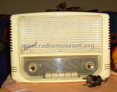
Rekord 176
Emud, Ernst Mästling; Ulm
- Hersteller / Marke
- Emud, Ernst Mästling; Ulm
- Jahr
- 1957/1958
- Kategorie
- Rundfunkempfänger (Radio - oder Tuner nach WW2)
- Radiomuseum.org ID
- 21109
Klicken Sie auf den Schaltplanausschnitt, um diesen kostenlos als Dokument anzufordern.
- Anzahl Röhren
- 6
- Hauptprinzip
- Superhet allgemein; ZF/IF 468/10700 kHz
- Anzahl Kreise
- 6 Kreis(e) AM 9 Kreis(e) FM
- Wellenbereiche
- Langwelle, Mittelwelle und UKW (FM).
- Betriebsart / Volt
- Wechselstromspeisung / 125/220 Volt
- Lautsprecher
- Dynamischer (permanent) Ovallautsprecher
- Belastbarkeit / Leistung
- 3.5 W (Qualität unbekannt)
- Material
- Bakelit (Pressstoff)
- von Radiomuseum.org
- Modell: Rekord 176 - Emud, Ernst Mästling; Ulm
- Form
- Tischgerät, Tasten oder Druckknöpfe.
- Abmessungen (BHT)
- 320 x 210 x 150 mm / 12.6 x 8.3 x 5.9 inch
- Bemerkung
- Ferritantenne. Gehäuse Preßstoff braun, Mehrpreis für elfenbein 5,- DM.
Autotrafo, keine Netztrennung !!!
- Nettogewicht
- 4 kg / 8 lb 13 oz (8.811 lb)
- Originalpreis
- 176.00 DM
- Datenherkunft extern
- Erb
- Datenherkunft
- HdB d.Rdf-& Ferns-GrH 1957/58
- Literatur/Schema (1)
- -- Original-techn. papers.
- Weitere Modelle
-
Hier finden Sie 423 Modelle, davon 329 mit Bildern und 231 mit Schaltbildern.
Alle gelisteten Radios usw. von Emud, Ernst Mästling; Ulm
Forumsbeiträge zum Modell: Emud, Ernst Mästling: Rekord 176
Threads: 2 | Posts: 13
Hallo Forum,
ich habe hier ein Problem mit meinem EMUD Rekord 176. Nachdem ich es an das Stromnetz angeschlossen hatte, hatten sich die Röhren zwar „aufgeheizt“, das Radio blieb aber stumm. Beim Durchmessen der einzelnen Bauteile habe ich festgestellt, dass der Widerstand, der zwischen der Feinsicherung und der EZ 80-Röhre geschaltet ist, defekt ist. Laut Schaltplan hat dieser Widerstand einen Wert von 70 Ohm, die Wattleistung geht aus dem Plan leider nicht hervor. Zum Austausch hatte ich es zunächst mit einem 100 Ohm, 5 Watt Keramikwiderstand versucht, der jedoch beim Einschalten nahezu verglühte. Auch ein 68 Ohm Keramikwiderstand mit 17 Watt Leistungsaufnahme fing an, in Rauch aufzugehen, getestet ohne Röhrensatz.
Nun meine Frage: welche Wattleistung hat dieser Widerstand in Wirklichkeit, warum fängt selbst ein Widerstand mit der größten Leistungsaufnahme an, durchzubrennen (war bei meinem Radio nicht der Fall, da ich das Radio bei der ersten „Rauchschwade“ vom Netz getrennt habe).
Ich wäre für jede Anregung dankbar und bedanke mich schon mal im Voraus.
Gruß Stefan
Stefan Wüsthoff, 15.Aug.08
Gentlemen,
First, I hope everyone had a merry Christmas and a happy holiday no matter your religion and belief. Now, down to hobby business.
I have an Emud Record 176 (
The difference on this chassis is one of the power cord/mains conductors (before the primary on the power transformer) is connected to the chassis (through the power switch). I found this while locating the RF bypass caps. I use UL rated safety caps. I double checked this with an ohm meter and measured minimal resistance from one of the non-polarized plug tongs to the chassis. It is a good thing that I checked this with an Isolation Transformer.
Is this intentional?!
I have requested the schematic for this radio under the model number on this web site. But, until it is posted could/would someone look up the schematic for this unit and let me know how the mains power cord is supposed to be wired to the primary? OR email to me or post a schematic? And not to be too demanding, are there alignment instructions available?
Thanks in advance,
Paul.
PS - I attached a picture of a new way I opened up and gutted the can capacitor. I am sure many of you have this specialty tool that I used.
Anlagen
- Record 176 under chassis (85 KB)
- Open a can cap (85 KB)
Paul E. Pinyot † 2013, 28.Dec.06


