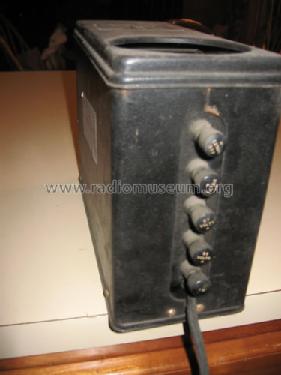
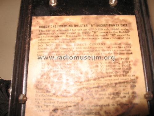
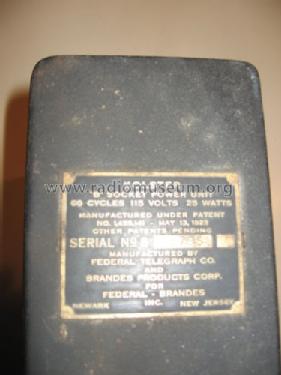
Kolster "B" Socket Power Unit
Federal Telegraph Company; Palo Alto, CA
- Pays
- Etats-Unis
- Fabricant / Marque
- Federal Telegraph Company; Palo Alto, CA
- Année
- 1927
- Catégorie
- Alimentation/stabilisateur de tension ou batterie ou chargeur
- Radiomuseum.org ID
- 195464
-
- alternative name: Kolster Radio Corporation
- No. de tubes
- 1
- Lampes / Tubes
- UX201A
- Gammes d'ondes
- - sans
- Tension / type courant
- Alimentation Courant Alternatif (CA) / 115 Volt
- Haut-parleur
- - - Pas de sortie basse fréquence
- Matière
- Boitier métallique
- De Radiomuseum.org
- Modèle: Kolster "B" Socket Power Unit - Federal Telegraph Company;
- Forme
- Modèle de table générique
- Dimensions (LHP)
- 3.75 x 7 x 9.5 inch / 95 x 178 x 241 mm
- Auteur
- Modèle crée par Mark Skala. Voir les propositions de modification pour les contributeurs supplémentaires.
- D'autres Modèles
-
Vous pourrez trouver sous ce lien 7 modèles d'appareils, 6 avec des images et 0 avec des schémas.
Tous les appareils de Federal Telegraph Company; Palo Alto, CA
Collections
Le modèle Kolster "B" Socket Power Unit fait partie des collections des membres suivants.
Contributions du forum pour ce modèle: Federal Telegraph: Kolster "B" Socket Power Unit
Discussions: 1 | Publications: 5
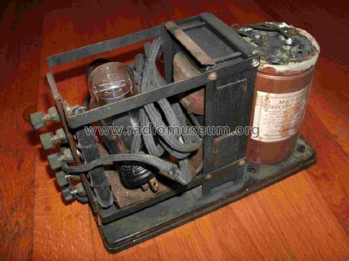
A while back I was working on this old power supply and had corresponded with someone in Radiomuseum on this. I am back on this project and hope to get some added help. Here is what I know:
The transformer in this unit is putting out 250 (+/-) volts DC. I tested the voltages at the taps and they are all wrong, indicating a bad resistor I think. The 135 VDC tap reads a full 250, the 90 vdc tap also reads 250. The 67 and 22 vdc taps all read low.
I substituted the big Mershon liguid filled cap with three smaller electrolytics rated for 600 vdc. (10uf as indicated on the original).
The resistor resistor reads open all the way up, except there is resistance between the top two (135 & 90) but not to the common below. The posibility of finding a replacement resistor is probably nill. Likewise any schematics.
My goal was to make this a functioning unit again, not just a display.
Can anyone offer some assistance?
Thanks in advance,
Mark
Mark Skala, 05.Oct.11


