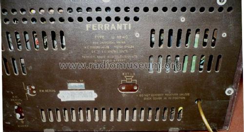
U1040
Ferranti, GB
- Country
- Great Britain (UK)
- Manufacturer / Brand
- Ferranti, GB
- Year
- 1961 ?
- Category
- Broadcast Receiver - or past WW2 Tuner
- Radiomuseum.org ID
- 151934
Click on the schematic thumbnail to request the schematic as a free document.
- Number of Tubes
- 7
- Main principle
- Superheterodyne (common); ZF/IF 470/10700 kHz; 2 AF stage(s)
- Tuned circuits
- 6 AM circuit(s) 8 FM circuit(s)
- Wave bands
- Broadcast, Long Wave and FM or UHF.
- Power type and voltage
- AC/DC-set / 200-250 Volt
- Loudspeaker
- Permanent Magnet Dynamic (PDyn) Loudspeaker (moving coil)
- from Radiomuseum.org
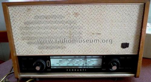
- Model: U1040 - Ferranti, GB
- Notes
- Same chassis as model U1032.
- Source of data
- -- Schematic
- Circuit diagram reference
- Radio and TV Servicing books (R&TVS) book
- Author
- Model page created by Keith Staines. See "Data change" for further contributors.
- Other Models
-
Here you find 217 models, 120 with images and 165 with schematics for wireless sets etc. In French: TSF for Télégraphie sans fil.
All listed radios etc. from Ferranti, GB
Forum contributions about this model: Ferranti, GB: U1040
Threads: 1 | Posts: 6
To any potential RMorg helpers,
I have just started some restoration work on a Ferranti U1040 which after some valve/tube replacement, is operating fairly well.
In order to try to rectify some distoration & intermittent sound loss, I have removed the chassis, and attached a couple of pictures of what I have found - despite working fairly well, there are the remains of what I think is a 0.01uf capacitor, which has the original wire connector at one end still soldered as can be seen.
I have tried for about an hour to see where the other end was attached, without success; perhaps the other end of the capacitor has been blown out of the radio somehow, I certainly can`t find it.
As far as I can see from the schematic, there are 3 such cpacitors fitted, and I have found the other two.
In order to replace these 3 `wax, caps`, I need to find out which capacitor it is that has blown, and where it should be connected within the chassis; apart from the one connection I still have (which is connected to the chassis itself). I cannot find a chassis layout in amongst all my sources.
Can anyone help me with this cap replacement please - this is a fairly good looking radio, and even without the blown cap operates adequately enough, but has the potential to work even better.
Thanks in advance for any assistance anyone can provide.
graham guy
Attachments
Graham GUY, 07.Jul.11