U1040
Ferranti, GB
- Produttore / Marca
- Ferranti, GB
- Anno
- 1961 ?
- Categoria
- Radio (o sintonizzatore del dopoguerra WW2)
- Radiomuseum.org ID
- 151934
Clicca sulla miniatura dello schema per richiederlo come documento gratuito.
- Numero di tubi
- 7
- Principio generale
- Supereterodina (in generale); ZF/IF 470/10700 kHz; 2 Stadi BF
- N. di circuiti accordati
- 6 Circuiti Mod. Amp. (AM) 8 Circuiti Mod. Freq. (FM)
- Gamme d'onda
- Onde medie (OM), lunghe (OL) e MF (FM).
- Tensioni di funzionamento
- Alimentazione universale (doppia: CC/CA) / 200-250 Volt
- Altoparlante
- AP magnetodinamico (magnete permanente e bobina mobile)
- Radiomuseum.org
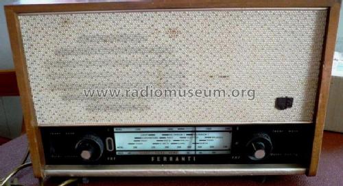
- Modello: U1040 - Ferranti, GB
- Annotazioni
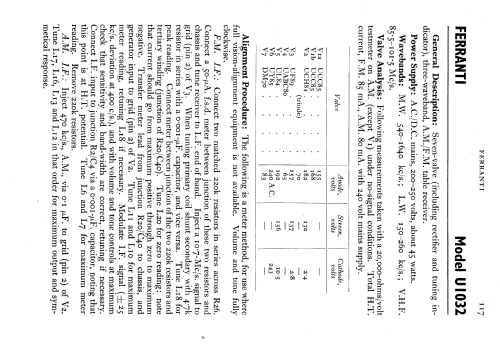
- Same chassis as model U1032.
- Fonte dei dati
- -- Schematic
- Riferimenti schemi
- Radio and TV Servicing books (R&TVS) book
- Autore
- Modello inviato da Keith Staines. Utilizzare "Proponi modifica" per inviare ulteriori dati.
- Altri modelli
-
In questo link sono elencati 219 modelli, di cui 125 con immagini e 166 con schemi.
Elenco delle radio e altri apparecchi della Ferranti, GB
Discussioni nel forum su questo modello: Ferranti, GB: U1040
Argomenti: 1 | Articoli: 6
To any potential RMorg helpers,
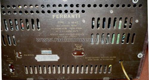
I have just started some restoration work on a Ferranti U1040 which after some valve/tube replacement, is operating fairly well.
In order to try to rectify some distoration & intermittent sound loss, I have removed the chassis, and attached a couple of pictures of what I have found - despite working fairly well, there are the remains of what I think is a 0.01uf capacitor, which has the original wire connector at one end still soldered as can be seen.
I have tried for about an hour to see where the other end was attached, without success; perhaps the other end of the capacitor has been blown out of the radio somehow, I certainly can`t find it.
As far as I can see from the schematic, there are 3 such cpacitors fitted, and I have found the other two.
In order to replace these 3 `wax, caps`, I need to find out which capacitor it is that has blown, and where it should be connected within the chassis; apart from the one connection I still have (which is connected to the chassis itself). I cannot find a chassis layout in amongst all my sources.
Can anyone help me with this cap replacement please - this is a fairly good looking radio, and even without the blown cap operates adequately enough, but has the potential to work even better.
Thanks in advance for any assistance anyone can provide.
graham guy
Allegati
Graham GUY, 07.Jul.11