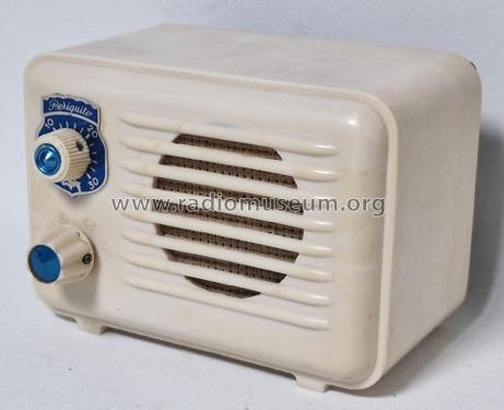
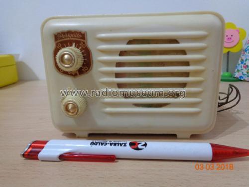
Periquito early
Freixa, L., Manufacturas de Radio (Monitor); Barcelona
- Land
- Spanien / Spain
- Hersteller / Marke
- Freixa, L., Manufacturas de Radio (Monitor); Barcelona
- Jahr
- 1950
- Kategorie
- Rundfunkempfänger (Radio - oder Tuner nach WW2)
- Radiomuseum.org ID
- 62500


Klicken Sie auf den Schaltplanausschnitt, um diesen kostenlos als Dokument anzufordern.
- Anzahl Röhren
- 3
- Datumskonflikt
- Das Modell-Datum widerspricht Röhren-Daten [ HCH81 (1952)]
- Hauptprinzip
- Geradeaus mit Diodengleichrichtung
- Anzahl Kreise
- 2 Kreis(e) AM
- Wellenbereiche
- Mittelwelle, keine anderen.
- Betriebsart / Volt
- Allstromgerät / 117 Volt
- Lautsprecher
- Dynamischer LS, keine Erregerspule (permanentdynamisch) / Ø 3 inch = 7.6 cm
- Belastbarkeit / Leistung
- 1.9 W (Qualität unbekannt)
- Material
- Plastikgehäuse (nicht Bakelit), Thermoplast
- von Radiomuseum.org
- Modell: Periquito [early] - Freixa, L., Manufacturas de
- Abmessungen (BHT)
- 5.1 x 3.7 x 3.5 inch / 130 x 94 x 89 mm
- Bemerkung
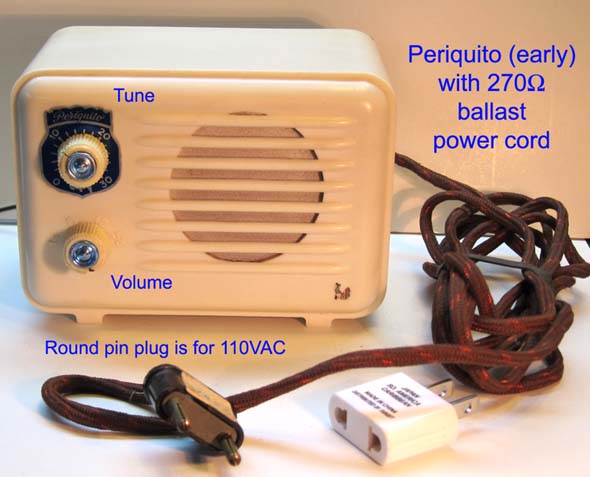
- 270 Ohm Ballast resistor in power cord wrapped around a flexible non-rubber, plastic insulator that did not become brittle after 60 years. The upper knob has a volume dial, but it controls tuning. The lower knob turns on the radio and controls volume, but has frequency markings around it embossed on the case.
- Datenherkunft extern
- Ernst Erb
- Datenherkunft
- Radio Historia y Técnica, J.J.E.
- Weitere Modelle
-
Hier finden Sie 18 Modelle, davon 15 mit Bildern und 2 mit Schaltbildern.
Alle gelisteten Radios usw. von Freixa, L., Manufacturas de Radio (Monitor); Barcelona
Sammlungen
Das Modell Periquito befindet sich in den Sammlungen folgender Mitglieder.
Forumsbeiträge zum Modell: Freixa, L.,: Periquito
Threads: 1 | Posts: 4
Fellow Radiophiles,
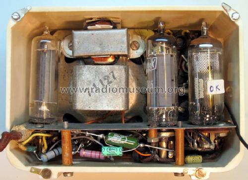
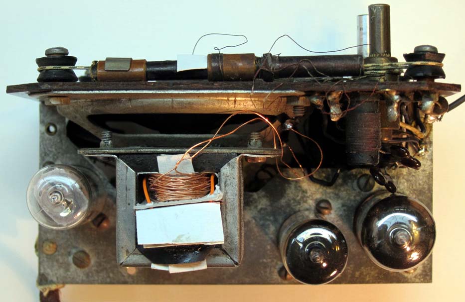
Recently, I got a very small model Periquito by Catalan radio maker Luis Freixa. My version is the early one with the ballast resistor for the series heater string in the power cord. later versions used an internal ballast resistor. I will share here what I learned from tracing it's circuit, repairing and aligning it.
Circuit operation
This radio has a unique 3-tube design with the HCH81 HL94 35W4 heaters wired in series with an external 270Ω power cord ballast to drop the external 110VAC to 77VAC at 150mA. One side of the power cord is wired to the chassis, which also serves as the ground system for the wire antenna. When operating this radio with an isolation transformer on the repair bench, it is necessary to ground the chassis for good reception. When plugged directly into 110VAC outlet, one plug-in orientation gives less hum. But do not ground the chassis if the radio is plugged directly into the mains.
After the radio is back in it's case keep in mind that the two holding screws under the case are electrically connected to the chassis and are therefor connected to one side of the power line. When the power switch is on, the chassis is directly connected to one side of the power plub. When the power switch is off, the chassis is tied to the other plug terminal via the the tube heaters. So, it is best to keep this radio over an insulated surface. I perfer this approach to rewiring the radio with a polarized plub, that has the neutral always tied to the chassis.

The power cord barely warms up while dissipating 6.5W, but it is still necessary to keep the power cord uncoiled to prevent it from overheating. The power cord ballast is in very good shape and it is made very differently from American ballast cords of the 1930's. The cord in the Periquito is entirely made of plastic materials, which have kept their resilience, while most of the 1930's ballast cords were usually made with rubber and asbestos. The rubber in these older cords usually hardens up, which tends to make the NiCr resistance wire break when the cord is flexed.
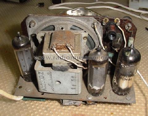
The 35W4 rectifier and it's circuit are common enough.
The HL94/30A5 audio power pentode is somewhat unusual. With it's 30V heater, It dissipates less power than the 35V or 50V 150mA series heater alternatives. However, the HL94/30A5 has 9.2mS of transconductance, which is noticeably higher that of the common 35C5 with only 5.8mS. If the 30A5 is hard to find, a good substitute is the 35EH5 with gm=12mS, but this may require reducing the cathode bias resistor from 150Ω to 62Ω. The 35EH5 may actually be an improvement over the 30A5 with it's higher gain and lower plate current. Every bit of gain counts in a 3 tube radio.
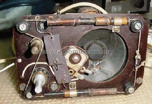
The front end is where this radio's design is unique. It uses the HCH81 Heptode/triode tube, but not in its usual frequency mixer and oscillator configuration. The heptode is wired in a reflex configuration as RF and AF amplifier, while the triode is wired as a simple diode detector. The input and output of the Rf stage have two permeability tuned circuits that are tuned together with movable slugs attached to the dial cord. The RF circuitry also employs inductively coupled regeneration with L4-slide from the tuned plate circuit to the tuned grid circuit to increase gain and selectivity in the single RF stage.
The detector low pass filter C9-Trim is adjustable and serves to control the regenerative feedback at lower frequencies. I was not able to determine conclusevely the phase relationship between the primary and secondary of the two RF transformers. This feedback is also mediated by the diode detector at the triode plate, so it could be said that a form of regenerative detection is present.
It is surprising to see the triode employed as a simple diode detector, as opposed to a grid leak detector configuration that would yield higher gain. However, this would have necessitated moving the gain control to the antenna circuit to avoid detector saturation on strong stations.
One curious coincidence is that the HCH81 heptode/triode and the EBF89 pentode/dual-diode pinouts are compatible in this design. However, the EBF89 heater requires 6.3V/300mA. The EBF89 would have given higher gain with it's gm=4.5mS; while the HCH81 has gm=2.4mS. I am not aware of a 12.6V/150ma heater version of the EBF89.
Note that there is no RF filter capacitor at R7 to block RF energy from the audio power pentode. the only RF filter is C5-black at the HL94 audio power pentode plate. The C5-black capacitor also serves to protect the plate circuit from high voltage spikes that would occur without a plate capacitor when the plate current is suddenly cutoff with a noise spike.
Some incidental RF filtering will also happen as the high impedance of the volume control is loaded by the input capacitance of the power pentode. This effect must be significant because the regenerative oscillations are more likely to occur with the volume control at full volume. Even backing off the volume control by about 10% of it's range is enough to kill the oscillation. When the regenerative feedack coil L4-slide is not coupled to tightly, there are no oscillations at any volume setting.
Repair
The power switch was dirty and measured 50Ω, so I cleaned it with DeOxit, and it is fine now.
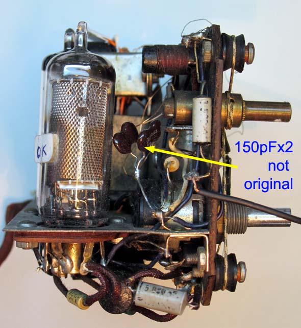
The original HL94 tube was weak, so I replaced it with a 30A5 equivalent. The electrolytic caps had already been replaced and I checked the other caps for leakage.
![]()
![]() The only serious repair problem was the burned out primary of the audio transformer. I thought of rewinding it, but that would be too many turns of fine wire without a mechanized winding setup. I resorted, instead, to a transformer transfusion. I took the primary winding of good small 120V/12V transformer in my junk box and placed it over the core of the original transformer with a card insulator over the iron core. Then I hand wound the secondary with heavier wire. The card insulators and electrical tape insure that the enameled windings never touch the core. I counted the turns on the primary with the goal to get a 27x turns ratio. The primary turns were never counted. The number you see is an estimate from the voltage/turns ratio and the known secondary turn count.
The only serious repair problem was the burned out primary of the audio transformer. I thought of rewinding it, but that would be too many turns of fine wire without a mechanized winding setup. I resorted, instead, to a transformer transfusion. I took the primary winding of good small 120V/12V transformer in my junk box and placed it over the core of the original transformer with a card insulator over the iron core. Then I hand wound the secondary with heavier wire. The card insulators and electrical tape insure that the enameled windings never touch the core. I counted the turns on the primary with the goal to get a 27x turns ratio. The primary turns were never counted. The number you see is an estimate from the voltage/turns ratio and the known secondary turn count.
![]()
![]()
![]()
 The only other significant repair was the creation of a missing screw in the one of the knobs.
I used a small carbide-fiber cutting wheel on my high speed hobby drill to cut two grooves at the end of a a 1" long 4-40 screw. This screw was used to tap the screw hole which had been worn smooth.
Then I cut away the sides of the the head of a short 4-40 screw and cut it's length to find the knob without protruding. The original slot remains on the screw.
The other knob is functional but has some of it's plastic broken away and I have not yet attempted this kind of reconstruction repair.
Alignment
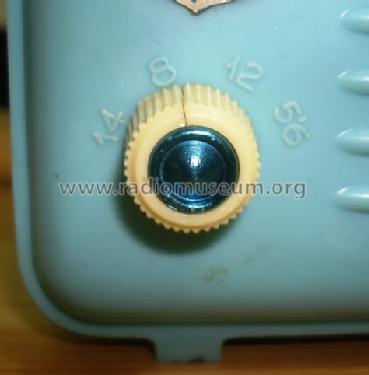
Perhaps the strangest thing in this radio is that the case markings for the tuning and volume knobs are reversed. The volume is adjustable from 14 to 5.5, while the tuning is from 0 to 30. Perhaps the case was designed well in advance of the chassis.
All the alignment adjustments in this radio, except for C9trim, are inductor adjustments. I found no alignment instructions for this radio, so I improvised.

This alignment sequence emerged from the experimentation:
0-If the radio is oscillating, move the positive feedback coil L4slide to the right to reduce it's coupling until all oscillations stop anywhere across the band.
1-Tune the low end of the band at 550kHz to get the iron slugs on the dial cord all the way into their coils.
2-Loosen the two small metal clamps that hold the coils in place and gently nudge the input and output coils along the top and bottom of the front panel to the left or right for peak signal output with a 550kHz input.
3-Move the tuning knob to the high end of the band at 1600kHz and apply a 1600kHz signal. Adjust the two small coils L2trim and L3 trim for peak output.
You may have to repeat and experiment with steps 1-3 to get good alignment across the band. After you have aligned with 550kHz and 1600kHz, you may want to touch up the aligment with two frequencies that are a little further from the end, like 650kHz and 1400kHz.
4-Now what is left is the RF regeneration adjustment. Two adjustments control regeneration. One is L4slide at the top coil and the other is the mica capacitor at the center of the front panel. The function of L4 is obvious: just move it left towards the other coils on the same form just before oscillations occur. Check for oscillations over the entire band.
5-The purpose of C9trim is less obvious, but it appears to also control regeneration. The inductive feedback from step 4 should favor the high end of the band, while the feedback path via C9trim should favor the low end of the band. I found that I had to add 300pF in parallel with this cap to obtain stability. This adjustment is less critical than step 4.
After all adjustments are complete, the two little metal clamps should be tightened. I also found it necessary to slip a small piece of card stock under the sliding coil L4slide to keep it stationary.
Prof. Rudolph has recently posted a very useful guide on how to drive a wire antenna input with an RF generator. I read the German language post with the Google translator. This is particularly relevant for radios like this one, that have no built-in loop antenna.
A few photos


Regards,
-Joe
Joe Sousa, 28.Nov.10