- Country
- United States of America (USA)
- Manufacturer / Brand
- General Electric Co. (GE); Bridgeport CT, Syracuse NY
- Year
- 1951 ?
- Category
- Broadcast Receiver - or past WW2 Tuner
- Radiomuseum.org ID
- 41947
-
- Brand: Musaphonic
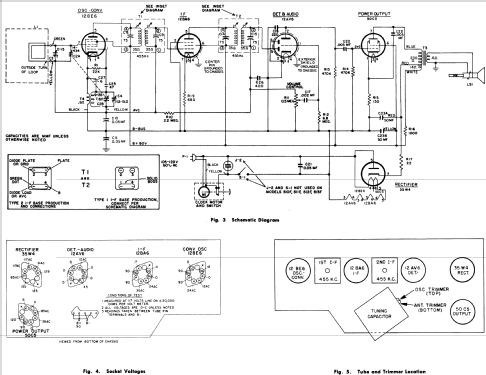
Click on the schematic thumbnail to request the schematic as a free document.
- Number of Tubes
- 5
- Main principle
- Superheterodyne (common); ZF/IF 455 kHz; 2 AF stage(s)
- Tuned circuits
- 6 AM circuit(s)
- Wave bands
- Broadcast only (MW).
- Power type and voltage
- Alternating Current supply (AC) / 60 Hz, 117V = 110 -120 Volt
- Loudspeaker
- Permanent Magnet Dynamic (PDyn) Loudspeaker (moving coil) / Ø 4 inch = 10.2 cm
- Material
- Plastics (no bakelite or catalin)
- from Radiomuseum.org
- Model: 516F - General Electric Co. GE;
- Shape
- Tablemodel with Clock ((Alarm-) Clock Radio).
- Dimensions (WHD)
- 11.5 x 6 x 5.5 inch / 292 x 152 x 140 mm
- Notes
-
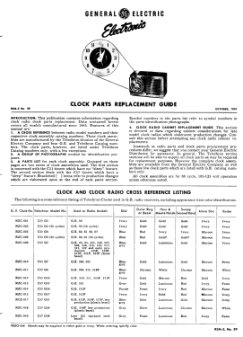
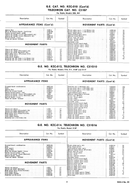
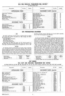
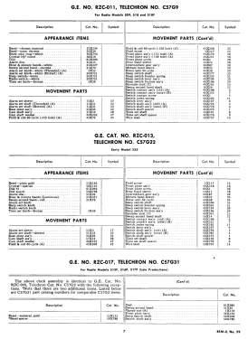
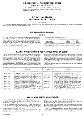
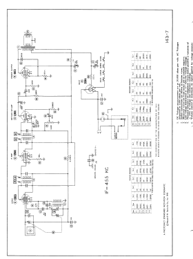
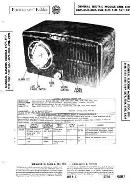
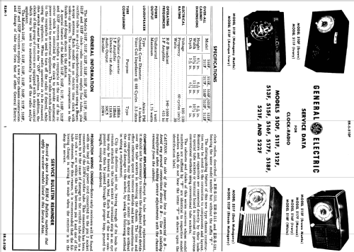
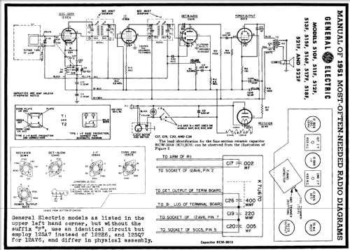
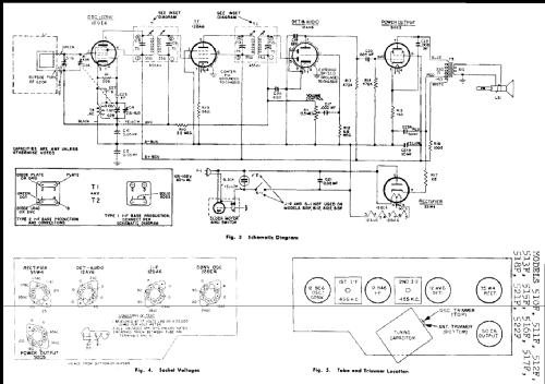
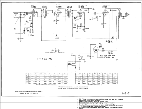
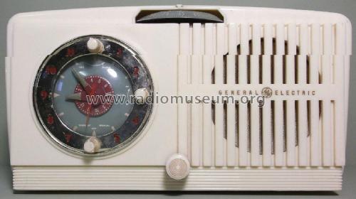
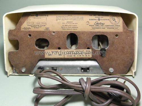
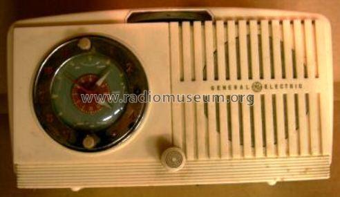
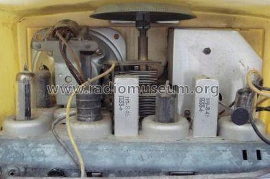
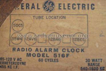
General electric model 516F is an AC operated superheterodyne receiver with electric clock.
- External source of data
- Ernst Erb
- Source of data
- Collector's Guide to Antique Radios 4. Edition
- Circuit diagram reference
- Rider's Perpetual, Volume 22, covering 1951
- Mentioned in
- The Radio Collector's Directory and Price Guide 1921 - 1965 (Beitman Radio Diagrams 1951)
- Literature/Schematics (1)
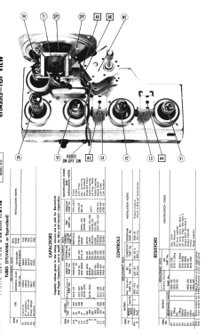
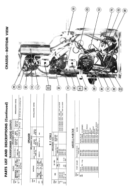
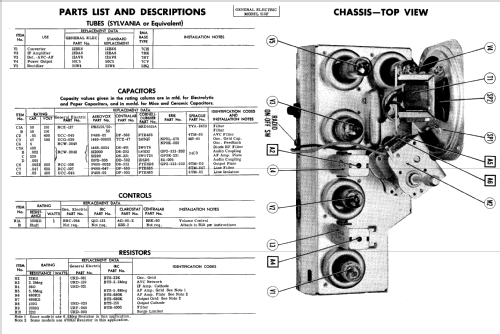
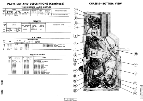
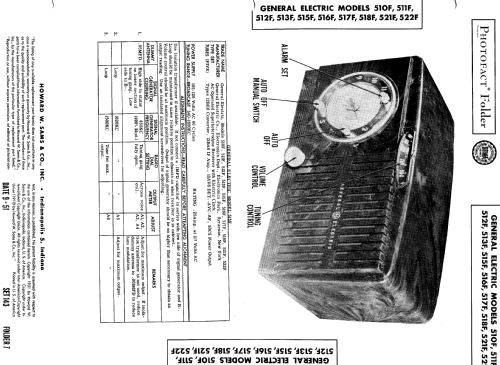
- Photofact Folder, Howard W. SAMS (Date 9-51, Set 143, Folder 7)
- Other Models
-
Here you find 2918 models, 2141 with images and 2044 with schematics for wireless sets etc. In French: TSF for Télégraphie sans fil.
All listed radios etc. from General Electric Co. (GE); Bridgeport CT, Syracuse NY
Forum contributions about this model: General Electric Co.: 516F
Threads: 1 | Posts: 1
General Electric516F USA import. It may be of interest to fellow enthustists How I fix this radio .Firstly I
-see if any previous work done. I replaced the tubes with a set of good tubes for testing .I don't switch on just yet. I check for shorts and the filter condenser capacitance ( was over 50uf ) -that was fine .I reform the condenser from 26mA to 0.5mA This may be done by placing the condenser in series with two 15-watt electric lamps(series connected) and a DC supply.When first connected the lamps will probably light ,after some time will cease to glow.I like to have a meter set to mA to see progress.Next job switch on Dead -mains switch open circuit I solder a wire link( for testing) -still dead -My mistake it is a clock radio I removed the clock at the beginning . The radio now works well. I don.t change resistors or condensers only, if I have to . I do check coupling condensers -That's it.
James Booth, 13.Jan.17
