- Produttore / Marca
- General Electric Co. (GE); Bridgeport CT, Syracuse NY
- Anno
- 1940–1942
- Categoria
- Radio (o sintonizzatore del dopoguerra WW2)
- Radiomuseum.org ID
- 42416
-
- Brand: Musaphonic
Clicca sulla miniatura dello schema per richiederlo come documento gratuito.
- Numero di tubi
- 9
- Principio generale
- Supereterodina a doppia / tripla conversione; ZF/IF 23150-27150,4300 kHz; Apparecchiatura speciale (descrivere nelle note)
- N. di circuiti accordati
- 13 Circuiti Mod. Freq. (FM)
- Gamme d'onda
- Solo modulazione di frequenza (FM)
- Tensioni di funzionamento
- Alimentazione a corrente alternata (CA) / 105-125 Volt
- Altoparlante
- - Per cuffie o amplificatori esterni
- Materiali
- Mobile in legno
- Radiomuseum.org
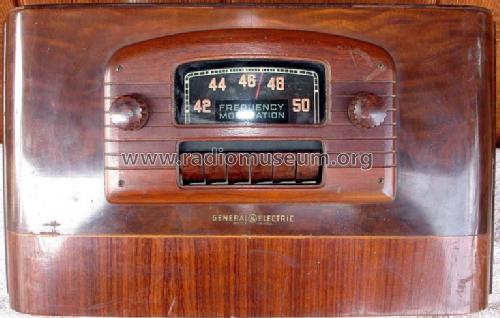
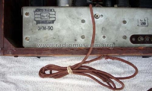
- Modello: JFM-90 - General Electric Co. GE;
- Forma
- Soprammobile con pulsantiera/tastiera.
- Dimensioni (LxAxP)
- 15.5 x 9 x 7.3 inch / 394 x 229 x 185 mm
- Annotazioni
-
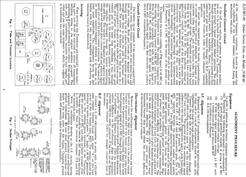
Phonograph or TV Audio connections. John F. Rider 13-76 "OSCILLATOR-CONVERTER CIRCUIT If the full noise reducing properties of frequency modulation are to be realized, the sensitivity of the Translator must be good enough to insure proper limiter operation. The gain through the intermediate frequency circuits is limited to that point beyond which lies instability. Hence a considerable amount of gain must be realized through the R. F. amplifier and converter circuits in order to insure adequate receiver sensitivity. To secure the required gain, the double superheterodyne or cascaded converter circuit is employed. It consists of tow converter tubes 6AB7's and an oscillator tube,7A4, with their associated circuits. The antenna circuit tunes tunes the band from 42 to 50 MC. The circuit between the two converters tunes from 23.15 to 27.15 MC. The oscillator voltage is inductively coupled to the grid of the first converter tube. This produces by heterodyne action a signal to which the inter-converter circuit is tuned. the first converter also conducts the oscillator signal through to the inter-converter circuit. Accordingly, the oscillator signal heterodynes with the tuned signal in the inter-converter circuit to produce an IF frequency of 4.3 MC at the output of the second converter. To illustrate the action consider an FM signal of 42 MC to which the Translator is tuned. The oscillator frequency for this setting of the tuning control is 18.85 MC signal and it heterodynes in the 1st converter tube with the 42 MC signal to form 23.15 MC (42-18.85). This 23.15 MC signal, in turn, beats with oscillator signal in the 2nd converter to produce the 4.3 MC intermediate frequency." Translator here means tuner.
- Fonte esterna dei dati
- Ernst Erb
- Fonte dei dati
- Rider's Perpetual, Volume 13 = 1942 and before
- Riferimenti schemi
- Rider's Perpetual, Volume 13 = 1942 and before
- Letteratura / Schemi (1)
- General Electric Radio Service Notes 1939-1942
- Letteratura / Schemi (2)
- Machine Age to Jet Age II (page 143.)
- Letteratura / Schemi (3)
- General Electric Folder 13-497-W for 1941.
- Altri modelli
-
In questo link sono elencati 2916 modelli, di cui 2140 con immagini e 2042 con schemi.
Elenco delle radio e altri apparecchi della General Electric Co. (GE); Bridgeport CT, Syracuse NY
Collezioni
Il modello JFM-90 fa parte delle collezioni dei seguenti membri.

