- Country
- United States of America (USA)
- Manufacturer / Brand
- General Electric Co. (GE); Bridgeport CT, Syracuse NY
- Year
- 1933 ?
- Category
- Broadcast Receiver - or past WW2 Tuner
- Radiomuseum.org ID
- 126156
-
- Brand: Musaphonic
Click on the schematic thumbnail to request the schematic as a free document.
- Number of Tubes
- 5
- Main principle
- Superhet with RF-stage; ZF/IF 175 kHz; 2 AF stage(s)
- Tuned circuits
- 5 AM circuit(s)
- Wave bands
- Broadcast (MW) and Tropical/Marine/Police Band(s) = 150-200m.
- Power type and voltage
- Alternating Current supply (AC) / 115 Volt
- Loudspeaker
- Electro Magnetic Dynamic LS (moving-coil with field excitation coil)
- Material
- Wooden case
- from Radiomuseum.org
- Model: K-52 - General Electric Co. GE;
- Shape
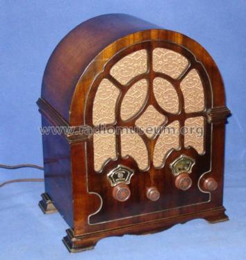
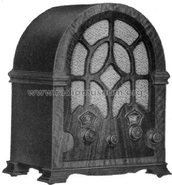
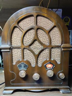
- Table-Cathedral-Type (upright, round top or gothic arch, not rounded edges only).
- Dimensions (WHD)
- 12 x 14.5 x 8.5 inch / 305 x 368 x 216 mm
- Notes
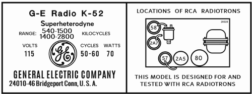
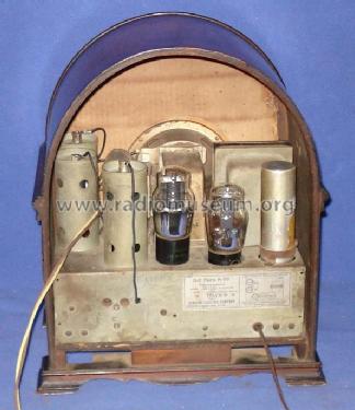
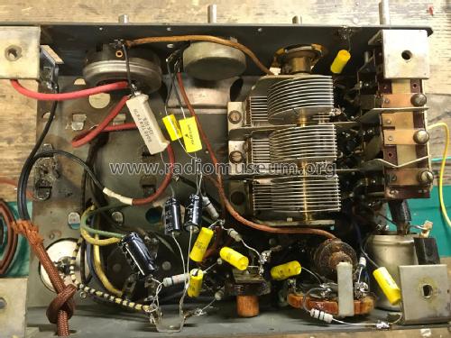
- The General Electric model K-52 has been made with the chassis R-28-P which is listed under RCA Victor. This chassis received more than a dozen different cabinets, from simple table models to consoles. There are two very similar schematics, one is for RCA Victor 110, 111 and 115 - see Beitman 1-179 and the other for the chassis R-28-P - see Beitman 1-169. Also Rider's brings as RCA R28 (3-4) and R28P (4-29). The power consumption is 70W; Range: BC 540-1500 kc; SW: 1400-2800 kc. The tube 58 is the RF amplifier, the 2A7 first detector/oscillator. There is no IF tube but a 3 circuit band filter, followed by the tube57 as second detector and power amplifier 2A5. Thus the receiver GE K-52 has only 5 tuned circuits pus a tickler coil (L6) for the IF.
- Circuit diagram reference
- Beitman Radio Diagrams Vol. 1, 1926-1938
- Mentioned in
- Machine Age to Jet Age II (page 144.)
- Literature/Schematics (1)
- Cathedral & Tombstone Radios (page 121.)
- Other Models
-
Here you find 2956 models, 2171 with images and 2069 with schematics for wireless sets etc. In French: TSF for Télégraphie sans fil.
All listed radios etc. from General Electric Co. (GE); Bridgeport CT, Syracuse NY
Collections
The model K-52 is part of the collections of the following members.
