- Country
- United States of America (USA)
- Manufacturer / Brand
- Granco Products, Inc.; Long Island City (NY)
- Year
- 1962
- Category
- Pre-stage (adaptor for SW/FM/VHF/UHF incl. built-in), Frequency converter
- Radiomuseum.org ID
- 150628
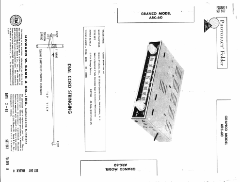
Click on the schematic thumbnail to request the schematic as a free document.
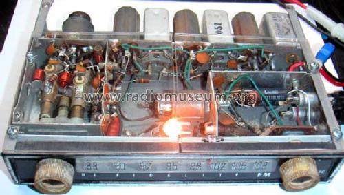
- Number of Tubes
- 5
- Main principle
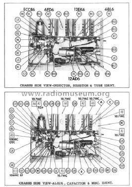
- Superhet with RF-stage; ZF/IF 10700 kHz; something special ? Please give information (notes)
- Tuned circuits
- 9 FM circuit(s)
- Wave bands
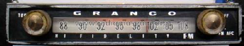
- FM Broadcast Band Only
- Power type and voltage
- Storage and/or dry batteries / 12.6 Volt
- Material
- Metal case
- from Radiomuseum.org
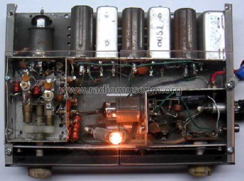
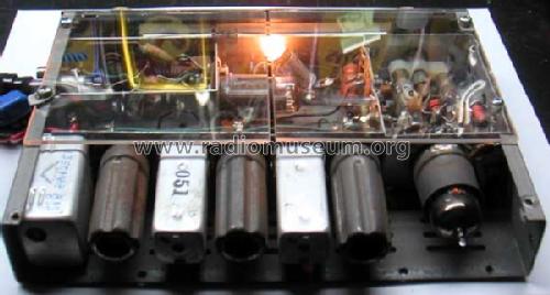
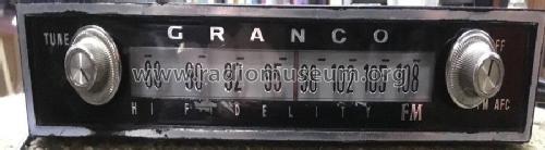
- Model: ARC-60 - Granco Products, Inc.; Long
- Shape
- Chassis only or for «building in»
- Dimensions (WHD)
- 8 x 6 x 1.5 inch / 203 x 152 x 38 mm
- Notes
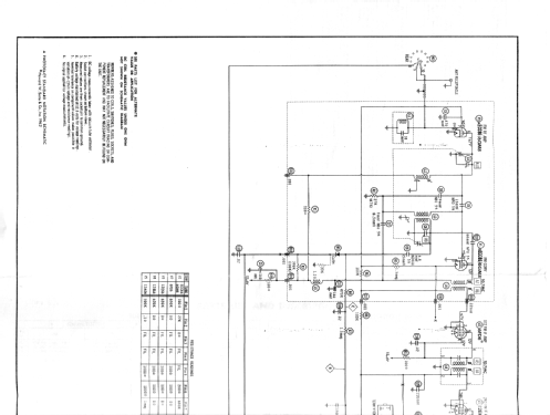
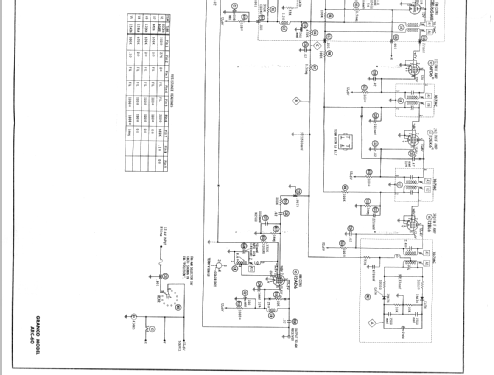
- Very unusual FM converter for the car, modulates AM at 1350kHz with 12AD6. B+ is 12V. Includes Varactor AFC. Grounded grid preamp converter drives additive triode converter
- Source of data
- Photofact Folder, Howard W. SAMS
- Author
- Model page created by Joe Sousa. See "Data change" for further contributors.
- Other Models
-
Here you find 40 models, 34 with images and 30 with schematics for wireless sets etc. In French: TSF for Télégraphie sans fil.
All listed radios etc. from Granco Products, Inc.; Long Island City (NY)
Collections
The model ARC-60 is part of the collections of the following members.
Forum contributions about this model: Granco Products, Inc: ARC-60
Threads: 1 | Posts: 12
Fellow radiophiles,
The Granco ARC60 FM converter for the car has a built-in AM modulator circuit that could be used as a home AM transmitter. One advantage of this circuit is it's low 12.6V operation. Otherwise, converter tubes such as the 12BE6 have been popular tubes for use in home am transmitters. (use 6BY6 or similar with sharp cutoff, as described by Jacob in the next post. 2009-10-22)

C25 is the last FM detector filter, and passes audio into the modulator through the bandpass filter comprised by R14, C26, C27, R17. The audio modulation input for the tube is the first suppressor grid at pin 7. This grid has a remote cutoff characteristic because it is normally used for AGC when this tube is used as an AM converter at the front end of an AM car radio.
R15 may be grounded or tied to 12.6V via a 390k resistor that is not present in this schematic. Use whichever configuration makes the oscillator work reliably. This is probably what was done at the factory.
L8 is a common local oscillator coil that is found in most radios.
L9 is a 1mH RF choke, and could be replaced with a tuned loop for effective magnetic radiation of the signal.
The data sheet for the 12AD6 has these conversion transconductance values for three bias levels at G3:
G3=0V > Gc=260uS
G3=-1.8V > Gc=20uS
G3=-2.2V > Gc=5uS
These values and the grid leak bias of -0.8V suggest that the audio modulation input should not be much above 1Vp-p.
A low impedance earphone output of a CD player driving pin 7 directly may give good results.
Don't expect low distortion modulation much beyond 50%.
One clear advantage of this type of home am transmitter is that the local oscillator runs at a fixed amplitude, and it is it's output that is modulated by G3. This reduces, or eliminates, oscillator regrowth distortion when the modulation is too deep with a plate modulated oscillator.
Another useful characteristic of this oscillator is that the separation between the tank circuit and the output reduces the effect that the antenna has on frequency.
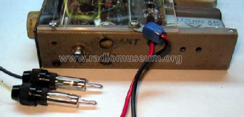
If your AM radios have a wire antenna, then a wire antenna should be tied to the antenna output of this circuit.
If your AM radios have a loop antenna, or ferrite stick antenna, then you should use a tunned loop in place of L9. This tuned loop could be a ferrite stick, or a home made loop. If you don't tune the loop. the reach of the transmission will be reduced.
In my case, I simply drive an external tuned ferrite stick antenna, without any modifications to the Granco. This setup has a range of about 3 feet. The existing 10k plate resistor widens the bandwidth of the loop by at least a factor of 10.
For more examples of AM transmitters check the list that is included in 1.5V AM tube transmitter.
Regards,
-Joe
Joe Sousa, 17.Oct.09