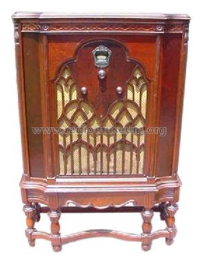
Majestic 310-B Twin Speaker
Grigsby-Grunow (-Hinds) Co. (Majestic pre 1933); Chicago (IL)
- Pays
- Etats-Unis
- Fabricant / Marque
- Grigsby-Grunow (-Hinds) Co. (Majestic pre 1933); Chicago (IL)
- Année
- 1932 ??
- Catégorie
- Radio - ou tuner d'après la guerre 1939-45
- Radiomuseum.org ID
- 43633


Ebay 260638152281

Ebay 260638152281

Ebay 260638152281

Ebay 260638152281

Ebay 260638152281
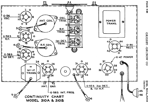
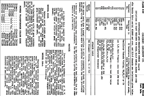
Cliquez sur la vignette du schéma pour le demander en tant que document gratuit.
- No. de tubes
- 7
- Principe général
- Super hétérodyne avec étage HF; FI/IF 175 kHz
- Circuits accordés
- 6 Circuits MA (AM)
- Gammes d'ondes
- PO uniquement
- Tension / type courant
- Alimentation Courant Alternatif (CA) / 110 Volt
- Haut-parleur
- HP dynamique à électro-aimant (électrodynamique)
- De Radiomuseum.org
- Modèle: Majestic 310-B Twin Speaker - Grigsby-Grunow -Hinds Co.
- Source extérieure
- Ernst Erb
- Source du schéma
- Rider's Perpetual, Volume 3 = 1933 and before
- Littérature
- Rider's Changes 9-2
- D'autres Modèles
-
Vous pourrez trouver sous ce lien 201 modèles d'appareils, 122 avec des images et 157 avec des schémas.
Tous les appareils de Grigsby-Grunow (-Hinds) Co. (Majestic pre 1933); Chicago (IL)
Contributions du forum pour ce modèle: Grigsby-Grunow -: Majestic 310-B Twin Speaker
Discussions: 1 | Publications: 3
The capacitor bypass block is not labeled at least not in any documentation that I can find.
It has 8 capacitors inside and has10 wires and 3 terminals.
I'm hoping someone can help me determine which wire/terminal belongs to which capacitor. I want to replace all of them. I have toyed with idea of taking the block out opening it up to see if each one is labled inside.
I'm attaching photos and a sketch I made showing where the wires/terminal go.
Any help/advice would be greatly appreciated.
Jim
Pièces jointes
- CapByPass_Block (241 KB)
- CapByPass_Block2 (248 KB)
- CapByPass_Block3 (289 KB)
- Majestic310B_Sketch (151 KB)
James Hochstetler, 26.Feb.22