Grimes Own Kit Inverse Duplex Reflex System
Grimes, David Inc.; Staten Island, NY
- Country
- United States of America (USA)
- Manufacturer / Brand
- Grimes, David Inc.; Staten Island, NY
- Year
- 1926/1927
- Category
- Kit (Parts plus instruction) or building instructions only
- Radiomuseum.org ID
- 191421
Click on the schematic thumbnail to request the schematic as a free document.
- Number of Tubes
- 5
- Main principle
- TRF without regeneration; 3 AF stage(s); Reflex
- Tuned circuits
- 3 AM circuit(s)
- Wave bands
- Broadcast only (MW).
- Power type and voltage
- Storage and/or dry batteries / Akku 6 + dry bat 22.5 + 4.5 (C) + 9 (C) + 90 + 135 Volt
- Loudspeaker
- - This model requires external speaker(s).
- Material
- Metal case
- from Radiomuseum.org
- Model: Grimes Own Kit Inverse Duplex Reflex System - Grimes, David Inc.; Staten
- Shape
- Tablemodel, Box - most often with Lid (NOT slant panel).
- Notes
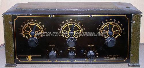
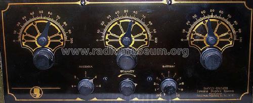
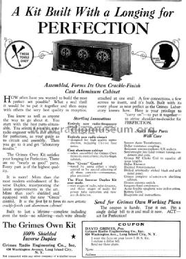
- Grimes tells in the ad from 1926, titled "A Kit Built With a Longing for PERFECTION" that assembled, it forms its own clackle-finish cast aluminium cabinet and calls it "The Grimes Own Kit". It has three dials (primary tuning control knobs) and below 3 smaller knobs for "Antenna", "Intensity" and "Battery". The inscription on the right reads: "David Grimes Inverse Duplex System, patented Grimes Radio Engineering Co. Inc. N.Y.". We added the word reflex to be found also under this.
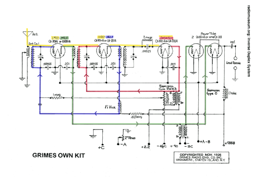
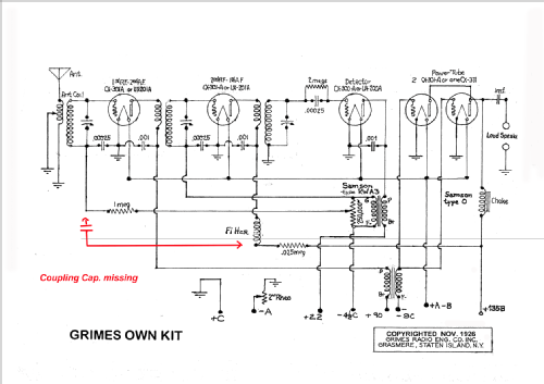
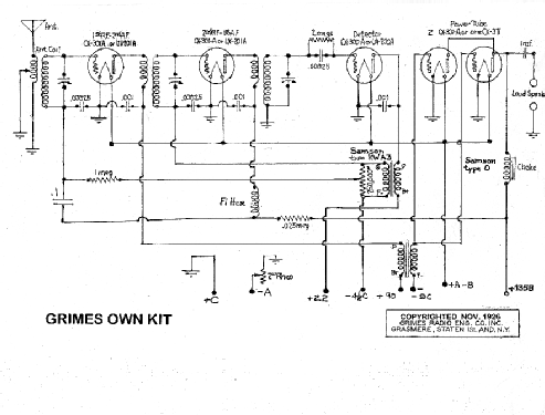
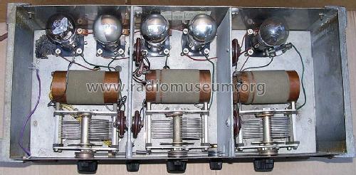
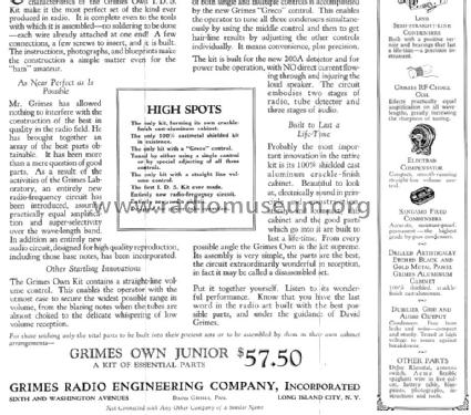
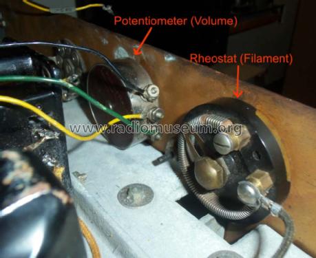
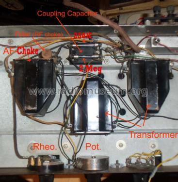
The detector tube UX200A gets a "B" voltage of 22.5 volts and the first tube gets the 90 volts "B" (anode). The power tubes get a grid bias of - 9 volts (C). The output tubes can be either 2 x CX301A in parallel or one CX371 which we believe should read CX371A and would be a UX171A. Interesting is some information about the parts: Samson Auto Transformers, DeJur resistance coupling, Benjamin non-microphonic UX sockets, Semi-straight line Lind vernier tuning condensers and coils, Grimes RF Choke Coil, DeJur rheostat, Electrad potentiometer, Sangamo fixed condensers, Acme flexible spaghetti wire in five colors, etc. "The kit is built for the new 200A detector and for power tube operation, with NO direct current flowing through and injuring the load speaker. The circuit embodies two stages of radio, tube detector and three stages of audio."<
There is also a reduced kit with the essential parts called Junior
See also the Inverse Duplex Reflex 4D or sometimes called 4DL.
- External source of data
- Don Patterson
- Literature/Schematics (1)
- Advertisement
- Author
- Model page created by Ernst Erb. See "Data change" for further contributors.
- Other Models
-
Here you find 17 models, 14 with images and 8 with schematics for wireless sets etc. In French: TSF for Télégraphie sans fil.
All listed radios etc. from Grimes, David Inc.; Staten Island, NY
Forum contributions about this model: Grimes, David Inc.;: Grimes Own Kit Inverse Duplex Reflex System
Threads: 1 | Posts: 1
First of all: the Inverse Duplex System is just another way of reflexing.
The particular difference lays in the signal processing sequence. While the RF goes througe 1st tube, 2nd tube to Det., the Af is first routed through the 2nd tube (which consequently is 2nd RF and 1st AF), then through the 1st tube (1st RF and 2nd AF).
The tube sequence for the complete signal chain is 1 - 2 - 3 - 2 - 1 - 4. The AF chain is inverted to the RF chain.
The straightforward arrangement for comparable performance would be 1 - 2 - 3 - 4 - 5 - 6, hence 2 tubes more.
Honestly: I cannot see any particular advantage by inversing. One idea might have been to balance the combined RF+AF peak amplitude a little. The weak RF at the input does not much harm to the higher audio level, while the 2nd tube, exposed to higher RF level gets less on top by the lower audio. May be, who knows....
Konrad Birkner † 12.08.2014, 07.Feb.11
