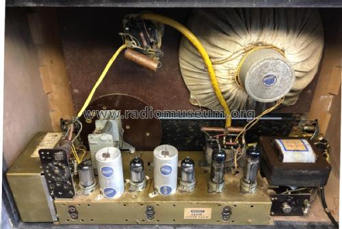
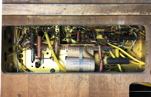
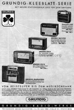
- Pays
- Allemagne
- Fabricant / Marque
- Grundig (Radio-Vertrieb, RVF, Radiowerke); Fürth/Bayern
- Année
- 1950/1951
- Catégorie
- Radio - ou tuner d'après la guerre 1939-45
- Radiomuseum.org ID
- 1881
-
- alternative name: Grundig Portugal || Grundig USA / Lextronix
Cliquez sur la vignette du schéma pour le demander en tant que document gratuit.
- No. de tubes
- 6
- Principe général
- Super hétérodyne (en général); FI/IF 468 kHz
- Circuits accordés
- 6 Circuits MA (AM)
- Gammes d'ondes
- PO, GO, plusieures bandes OC et préparé FM
- Tension / type courant
- Alimentation Courant Alternatif (CA) / 110-240 Volt
- Haut-parleur
- HP dynamique principe inconnu
- Matière
- Boitier en bois
- De Radiomuseum.org
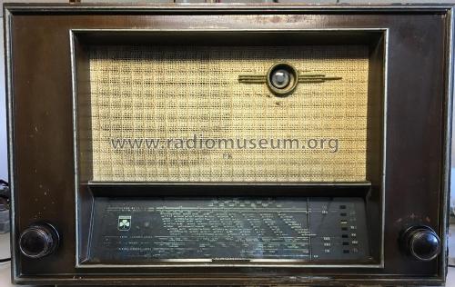
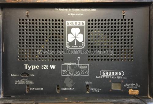
- Modèle: 326W - Grundig Radio-Vertrieb, RVF,
- Forme
- Modèle de table profil bas (grand modèle).
- Prix de mise sur le marché
- 326.00 DM
- Source
- Radiokatalog Band 1, Ernst Erb
- Source du schéma
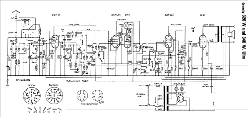
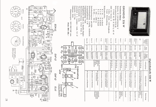
- Lange Schaltungen der Funkindustrie, Buch 4
- Littérature
- Funkschau (5009)
- D'autres Modèles
-
Vous pourrez trouver sous ce lien 6219 modèles d'appareils, 5452 avec des images et 4216 avec des schémas.
Tous les appareils de Grundig (Radio-Vertrieb, RVF, Radiowerke); Fürth/Bayern
Contributions du forum pour ce modèle: Grundig Radio-: 326W
Discussions: 1 | Publications: 2
Fellow Radiophiles,
Hum-bucking has surfaced several times in the forum with descriptions of methods to cancel residual hum in the power supply with an injection of hum of equal amplitude and shape, but opposite polarity.
One such method uses a tap at the audio output transformer and was used frequently in radios with a single ended pentode output in the 1950's and 1960's.
In Post #5 of Repair of Siemens H42 Olaf Krischer starts a conversation about this transformer tap with a supposition that this tap was primarily designed to cancel single ended transformer magnetizing current.
In Post#6, Hans Knoll shows the Grundig 326W as an example, and gives some very useful transformer data.
I added some notes to the schematic that was uploaded by Hinrich Grensemann. The transformer data came from Hans' post:
In Post#7, Prof Rudolph presents calculations to show how insignificant the magnetization current effect is, and thus makes the case for Hum/ripple cancellation.
Ripple/Hum Cancellation Requirements and Calculation
There are three important requirements for this ripple/hum cancellation method to work:
- The amplitude of the cancelling hum must match the hum to be cancelled
- The polarity of the cancelling hum must oppose the hum to be cancelled
- The shape of the cancelling hum/ripple must be as close as possible to the shape of the hum/ripple to be cancelled.
This last requirement limits the hum cancellation to the hum that is present at the Power pentode plate because the shape of the hum for the lower voltage supply that supplies the radio is not only much smaller, but it is also much smoother with a very different shape that looks like a 100Hz sinewave.
The ripple at the top of the first filter capacitor with 40uF is a 100Hz sawtooth wave with a fast rise from the rectifier conduction for about 2ms and a slow decay from the load current for 8ms. The 100Hz frequency comes from the Full Wave rectification of the 50Hz supply voltage.
The plate currents listed in the schematic add up to 45.9mA and constitude the discharge current for the first filter cap. A simple calculation using I=C*DV/DT, shows the hum/ripple voltage at the first filter cap, DV is 9V, if DT=8ms, C=40uF and I=45.9mA.
The expected p-p ripple at the first supply filter 40uF cap is 9Vp-p in the form of a 100Hz saw-tooth wave.
This 9Vp-p ripple is present at the input power supply tap of the output transformer, and appears nearly unattenuated at the EL41 Pentode plate because the 7k impedance of the transformer primary is a low impedance and little hum is dropped across it.
If the plate impedance at the pentode plate were infinite, the plate side of the transformer primary would appear to be floating, and none of the 9V sawtooth ripple would appear at the transformer secondary.
The following curve family and table show the typical operating characteristics for the EL41 as a class A singled ended power amplifier.
This pentode has a specified 40kOhm internal plate impedance with a grounded cathode. The unbypassed 150_Ohm cathode resistor works with the 10mS (=1/100_Ohms) transconductance to increase the internal plate resistance by 250/100=2.5. This brings the plate impedance to 100kOhms.
This 100kOhm plate impedance now serves as a load for the ripple presented to the audio output transformer primary, and about 9V*7k/107k=0.6Vp-p of ripple is dropped across the primary. This calculation is still an approximation because the reflected speaker impedance near 100Hz is likely to differ from the ideal 7kOhm primary impedance. In any case, the ripple cancelation does not depend directly on speaker loading because it affects both sections of the primary equally.
This 0.6Vp-p 100Hz sawtooth is the hum/ripple across the primary that we aim to cancel.
A similar voltage drop estimation can be done for the other end of the primary with the 1kOhm load that drives the high voltage in the rest of the radio.
In essence, we have a bridge cancellation arrangement, with one arm of the bridge as 100K and 7k, and the other arm of the bridge as 1k and 11R, but with 25:1 coupling between the 7k and 11R impedances that leads to a very good match in voltages at the to ends of the primary, which means that ripple/hum is cancelled.
However, the following calculation shows over compensation.
The A term is the ripple across the uncompensated 7k primary.
The B term is the transformed voltage from small 11_Ohm section, as it appears at the 7K section.
For good cancellation, the A and B terms should match. This calculation shows that these values lead to gross over-cancelation, such that the ripple is increased from 0.6Vp-p to -1.7Vp-p.
For a sanity check in my transformer calculations, which can be tricky, if you are out of practice, I ran a quick LTspice-IV simulation that confirmed my calculation.
I got a good match when I reduced the cancellation ripple by replacing the 1k resistor with a 4k resistor. I also got a good match when I changed the turns ratio between primary sections from 25.4 to 100.
Any comments to resolve this discrepancy, or any error in my calculations or assumptions would be welcome.
Hum compensation dependencies
Considering the various elements involved in this calculation, it should be expected that as the tube ages, and the 100k plate impedance rises, the ripple will be over compensated, and hum should be heard.
If the value of the kathode resistor is too high or too low, the hum should also be worse. Adding a bypass cap across the 150R cathode resistor should also greatly increase hum.
You may wonder about the 2nF negative feedback cap from the plate to the cathode of the preamp. The impedance of this cap at 100Hz is 800kOhms, so it should have little loading effect on the output transformer, otherwise a compensating cap would be needed in parallel with the 1k supply resistor.
Note that this simple and modest level of ripple cancellation was made possible by the high plate impedance of a pentode. A triode would pose a dramatically more difficult problem, with it's very low internal plate impedance. In fact, this trick would not be worthwhile for a triode load because the required value and turns ratio at the primary tap would cause significant audio power loss. A triode amplifier requires a power supply with much lower ripple.
The power loss due to the 1k resistor load on the primary of the transformer discussed above is negligible.
Regards,
-Joe
Joe Sousa, 27.Dec.09
