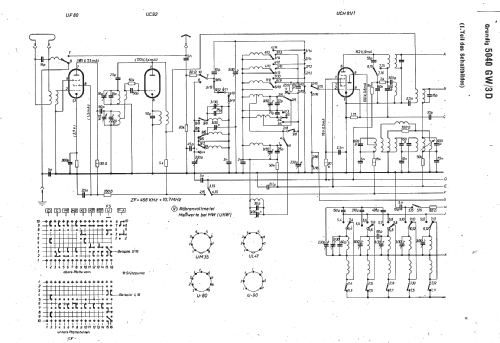
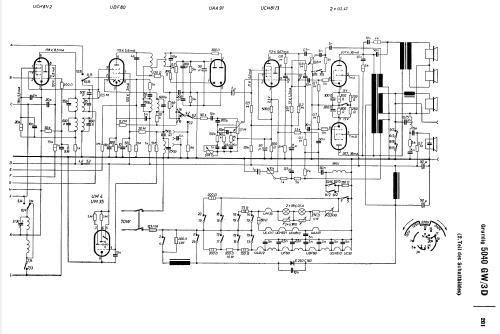
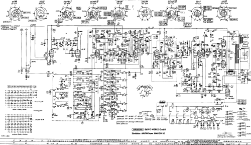
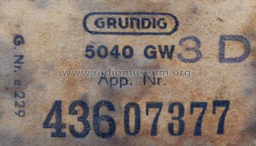
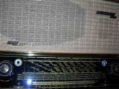
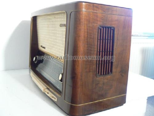
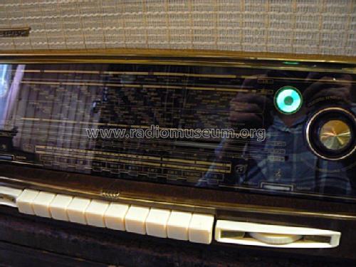
Konzertgerät 5040GW/3D
Grundig (Radio-Vertrieb, RVF, Radiowerke); Fürth/Bayern
- Paese
- Germania
- Produttore / Marca
- Grundig (Radio-Vertrieb, RVF, Radiowerke); Fürth/Bayern
- Anno
- 1954/1955
- Categoria
- Radio (o sintonizzatore del dopoguerra WW2)
- Radiomuseum.org ID
- 2041
-
- alternative name: Grundig Portugal || Grundig USA / Lextronix


Clicca sulla miniatura dello schema per richiederlo come documento gratuito.
- Numero di tubi
- 10
- Principio generale
- Supereterodina con stadio RF; ZF/IF 468/10700 kHz; 3 Stadi BF
- N. di circuiti accordati
- 11 Circuiti Mod. Amp. (AM) 11 Circuiti Mod. Freq. (FM)
- Gamme d'onda
- Onde medie (OM), lunghe (OL), piú di 2 gamme di onde corte (> 2 x OC) e MF (FM).
- Tensioni di funzionamento
- Alimentazione universale (doppia: CC/CA) / 110; 125; 220; 240 Volt
- Altoparlante
- 4 altoparlanti
- Potenza d'uscita
- 8 W (qualità ignota)
- Materiali
- Mobile in legno
- Radiomuseum.org
- Modello: Konzertgerät 5040GW/3D - Grundig Radio-Vertrieb, RVF,
- Forma
- Soprammobile con pulsantiera/tastiera.
- Dimensioni (LxAxP)
- 706 x 444 x 318 mm / 27.8 x 17.5 x 12.5 inch
- Annotazioni
- Grundig Konzertgerät 5040GW/3D hat im Gegensatz zum Wechselstrom-Modell 5040W/3D keine Motorabstimmung. Additive Triodenmischung für die AM-Bereiche. Der VDRG-Katalog 1954/55 führt irrtümlich UF89 als UKW-Vorstufe, lediglich 1x UL41 als Endstufe.
- Peso netto
- 17.3 kg / 38 lb 1.7 oz (38.106 lb)
- Prezzo nel primo anno
- 565.00 DM
- Fonte dei dati
- HdB d.Rdf-& Ferns-GrH 1954/55 / Radiokatalog Band 1, Ernst Erb
- Letteratura / Schemi (1)
- -- Schematic
- Altri modelli
-
In questo link sono elencati 6214 modelli, di cui 5447 con immagini e 4211 con schemi.
Elenco delle radio e altri apparecchi della Grundig (Radio-Vertrieb, RVF, Radiowerke); Fürth/Bayern
Collezioni
Il modello Konzertgerät fa parte delle collezioni dei seguenti membri.
Discussioni nel forum su questo modello: Grundig Radio-: Konzertgerät 5040GW/3D
Argomenti: 2 | Articoli: 2
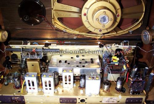
I am restoring a Grundig 5040W/3D and want to share photographs and what I have learned. I have uploaded some photographs from the initial steps of restoration. I used schematics and forum information from radiomuseum.org, thank you!
Here is what I have done so far:
Replaced almost ALL capacitors - most of the paper capacitors were bad, leaky or out of tolerance. They have been replaced with modern capacitors, some of them were replaced with "Orange Drop" capacitors (see photos). Special consideration given to any coupling capacitors such as the one that drives the grid of the EL-12 tube. A shorted or leaky capacitor here will place positive voltage on the grid causing the tube to conduct heavily and over heat. Evidence is seen in the cathode resistor of the EL-12 which may be burned or actually smoke!
Replaced selenium rectifier with modern silicon rectifiers - the original rectifier in the black can (probably selenium) had too much resistance and over heated, so the high voltages to the tubes was too low. Replaced with four 1KV 1A silicon diodes (see photo). The set really came alive after that! I left the old rectifier on the chassis and simply clipped its leads to preserve as much of the original look as possible.
Replaced some weak tubes. I used a tube tester to identify bad tubes and replaced them. All except the EL-12 and EF804 have American equivalents.
The full resolution (large) photos of the project are available on Photobucket at this LINK.
I will try to post more information as the project continues.
James Miller
James Miller, 16.Dec.11
http://www.radiomuseum.org/forum/additive_mischschaltungen_in_den_am_wellenbereichen.html
finden Sie ausführliche Informationen zum Thema Additive Mischung in den AM-Bereichen.
Andreas Steinmetz, 09.Jun.05