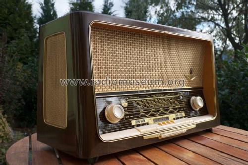
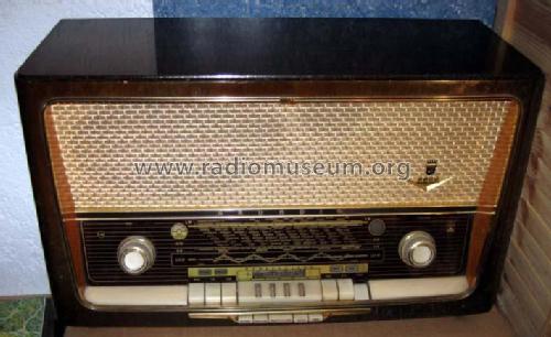
Konzertgerät 5088
Grundig (Radio-Vertrieb, RVF, Radiowerke); Fürth/Bayern
- País
- Alemania
- Fabricante / Marca
- Grundig (Radio-Vertrieb, RVF, Radiowerke); Fürth/Bayern
- Año
- 1957/1958
- Categoría
- Radio - o Sintonizador pasado WW2
- Radiomuseum.org ID
- 21142
-
- alternative name: Grundig Portugal || Grundig USA / Lextronix


ebay


�

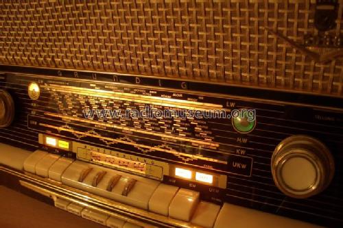


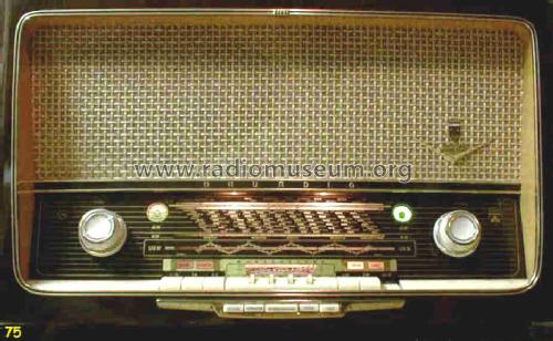
Gerät in Betrieb


Grundig 5088
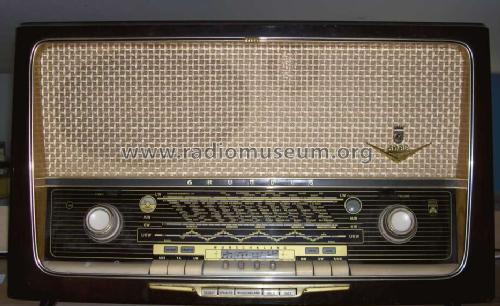
Gerät in restauriertem Zustand, spielt


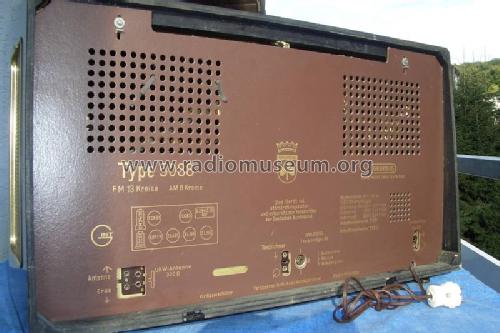
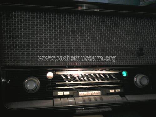
Linke Geräteseite
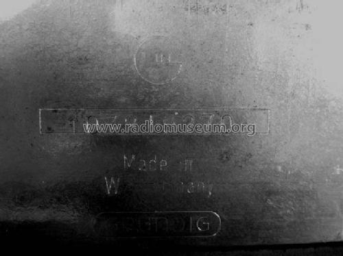
Seriennummer am Chassis
Haga clic en la miniatura esquemática para solicitarlo como documento gratuito.
- Numero de valvulas
- 8
- Principio principal
- Superheterodino en general; ZF/IF 460/10700 kHz; Reflex
- Número de circuitos sintonía
- 7 Circuíto(s) AM 11 Circuíto(s) FM
- Gama de ondas
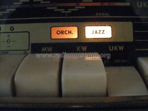
- OM, OL, OC y FM
- Tensión de funcionamiento
- Red: Corriente alterna (CA, Inglés = AC) / 110; 125; 160; 220 Volt
- Altavoz
- 4 Altavoces
- Potencia de salida
- 7 W (unknown quality)
- Material
- Madera
- de Radiomuseum.org
- Modelo: Konzertgerät 5088 - Grundig Radio-Vertrieb, RVF,
- Forma
- Sobremesa de botonera.
- Ancho, altura, profundidad
- 670 x 400 x 290 mm / 26.4 x 15.7 x 11.4 inch
- Anotaciones
-
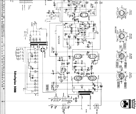
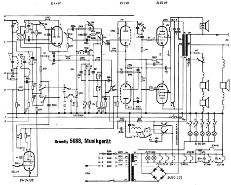
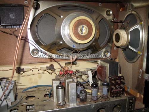
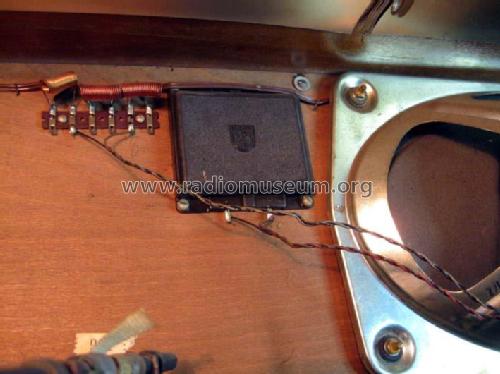
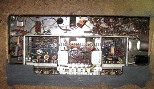
Drehbare Ferritantenne, Wunschklang-Register, Gegentakt-Endstufe.
Bei UKW wird die HF-Vorstufe in Reflexschaltung auch als erste FM-ZF-Stufe verwendet, das ergibt insgesamt 3 FM-ZF-Stufen.
Rückwandangabe 8 AM- und 13 FM-Kreise ist (werbewirksam) falsch.
- Peso neto
- 16.9 kg / 37 lb 3.6 oz (37.225 lb)
- Precio durante el primer año
- 448.00 DM
- Ext. procedencia de los datos
- Erb
- Procedencia de los datos
- HdB d.Rdf-& Ferns-GrH 1957/58
- Documentación / Esquemas (1)
- -- Original-techn. papers.
- Otros modelos
-
Donde encontrará 6240 modelos, 5481 con imágenes y 4238 con esquemas.
Ir al listado general de Grundig (Radio-Vertrieb, RVF, Radiowerke); Fürth/Bayern
Colecciones
El modelo Konzertgerät es parte de las colecciones de los siguientes miembros.
Contribuciones en el Foro acerca de este modelo: Grundig Radio-: Konzertgerät 5088
Hilos: 1 | Mensajes: 16
Gentlemen,
I am restoring a Grundig 5088 USA model and need some help with my first non-US radio restoration. I am using a schematic found at www.rad-io.de I have found it to be mostly accurate except for some of the audio frequency circuit architecture. There are differences.
A friend of the family has translated most of the words. So my questions are with the missing information below:
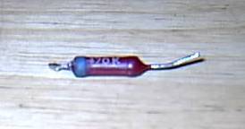
The resistors have the resitance printed on the body and a single color band on one end. What does this band represent and what are the values of the colors?
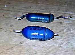
I have identified three types of fixed capacitors; Paper (Papier), Syrofome (Styrofier?) and Ceramic/mica (Keromic?). However, there are some paper capacitors that have a plastic like blue coating. The schematic clearly identifies these as paper. Is there more to these capacitors? Are they special (i.e., inverse temperature, resonant) capacitors?
Once I have replaced all of the paper and electrolytic capacitors (and the occational off tolerance resistor) RF alignment is next. The IF frequencies (10.7/460) and the transformers are identified. However, there are plenty of other adjustments with no explanation. Where might I find the alignment procedures?
Please forgive me if this information is readily available on the internet. If so, then please recomend an appropriate web site.
Thank you in advance for your time,
Paul.
I am restoring a Grundig 5088 USA model and need some help with my first non-US radio restoration. I am using a schematic found at www.rad-io.de I have found it to be mostly accurate except for some of the audio frequency circuit architecture. There are differences.
A friend of the family has translated most of the words. So my questions are with the missing information below:
The resistors have the resitance printed on the body and a single color band on one end. What does this band represent and what are the values of the colors?
I have identified three types of fixed capacitors; Paper (Papier), Syrofome (Styrofier?) and Ceramic/mica (Keromic?). However, there are some paper capacitors that have a plastic like blue coating. The schematic clearly identifies these as paper. Is there more to these capacitors? Are they special (i.e., inverse temperature, resonant) capacitors?
Once I have replaced all of the paper and electrolytic capacitors (and the occational off tolerance resistor) RF alignment is next. The IF frequencies (10.7/460) and the transformers are identified. However, there are plenty of other adjustments with no explanation. Where might I find the alignment procedures?
Please forgive me if this information is readily available on the internet. If so, then please recomend an appropriate web site.
Thank you in advance for your time,
Paul.
Paul E. Pinyot † 2013, 25.Jan.05