Stereo Console SO390-U/S
Grundig (Radio-Vertrieb, RVF, Radiowerke); Fürth/Bayern
- País
- Alemania
- Fabricante / Marca
- Grundig (Radio-Vertrieb, RVF, Radiowerke); Fürth/Bayern
- Año
- 1962/1963
- Categoría
- Radio - o Sintonizador pasado WW2
- Radiomuseum.org ID
- 102341
-
- alternative name: Grundig Portugal || Grundig USA / Lextronix

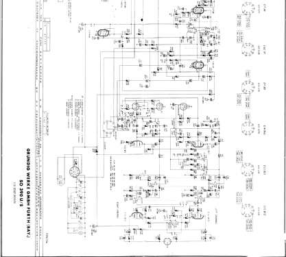


Haga clic en la miniatura esquemática para solicitarlo como documento gratuito.
- Numero de valvulas
- 14
- Principio principal
- Superheterodino en general
- Número de circuitos sintonía
- 8 Circuíto(s) AM
- Gama de ondas
- OM, dos OC y FM
- Especialidades
- Tocadiscos con cambiador autom.
- Tensión de funcionamiento
- Red: Corriente alterna (CA, Inglés = AC) / 115/220 Volt
- Altavoz
- 6 Altavoces
- Material
- Madera
- de Radiomuseum.org
- Modelo: Stereo Console SO390-U/S - Grundig Radio-Vertrieb, RVF,
- Forma
- Consola con botonera.
- Anotaciones
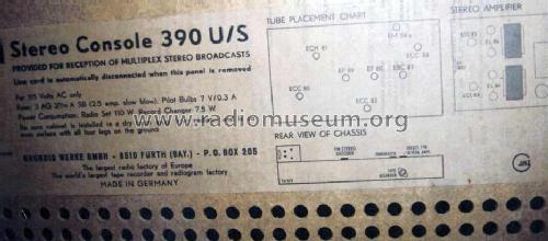
- This model is with its full name a Grundig export version for the USA: "Stereo Console 390 U/S" with a FM-Stereo Decoder and a Stereo Amplifier NF2 (2 x ECC83 and 4 x EL84). The back wall indicates 115 volts AC only but the set is for 115/220 Volts. Power consumption 110W plus Record Changer 7.5 Watt. Pilot Bulbs 7 V/0.3A. Push Buttons are for selecting OFF,PU,BC/MW,SW1,SW2,FM and STEREO,JAZZ,MULTUSONIC,ORCH,FA/AFT.
- Mencionado en
- -- Schematic
- Autor
- Modelo creado por Franz-Josef Haffner. Ver en "Modificar Ficha" los participantes posteriores.
- Otros modelos
-
Donde encontrará 6214 modelos, 5447 con imágenes y 4211 con esquemas.
Ir al listado general de Grundig (Radio-Vertrieb, RVF, Radiowerke); Fürth/Bayern
Contribuciones en el Foro acerca de este modelo: Grundig Radio-: Stereo Console SO390-U/S
Hilos: 1 | Mensajes: 7
hi,
i inherited this console fron my grandfather, Te power transformer was shot, because the filter caps failed, and someone put a wire in the fuse.
I sent the trasformer to repair it, but the technician dissapeared with the transfomer.
the console sat for years collecting dust in my house, and now i decided to finish the repair.
i will make a full recap and change the selenium rectifiers.
i started collecting info about it to figure out the specs of the transformer.
i found the schematic for the amplifier(NF2) and with this info i figured out some specs
For the B+:
312V[A*T]150Ma after rectifier.
312/1.44=217
first tap= 220V[A*T]150mA, but to be sure 220V[A*T]250mA.
If i consider the transformer regulation then 240V[A*T]250mA
For heaters the transformer have 2 windings:
first one for tubes in amp section and dial lamps.
The consumption for all tubes is around 4A
so this winding is 6,3V 4A
second one for tubes in pre/tuner section:
the consumption for all tubes is around 3A
So This winding is 6,3V[A*T]3A.
For bias
-16V after rectifier.
then it is adjusted with resistors to -11V
so this winding is 12V[A*T]30mA
so far so good, but then i came across the sams photofact for this model and the values are not the same for b+
the specs for the transformer are the following:
Secondary 1: 320V[A*T]150mA
secondary 2: 6,3V[A*T]2,4A
secondary 3: 6,3V[A*T]4A
secondary 4 15V[A*T]20mA.
also lists 330V after rectifier.
i'm a little confused. 320VAC is way to high even to get 330V after rectifier and considering the loss in selenium rectifiers and transformer regulation.
also i think 150 mA is too little.
i'm missing something?
also i'm curious about output trannies.
the sams photofact lists the following
primary: 5Kohms CT
secondary 3-4 ohms
i think 5K ist too little for 2 el84 Push-pull.
maybe is 5k between plate and center tap?, so the transformer is 10K?
Alfonso López-Martínez, 11.Feb.12