FM/AM 2-Band Digital radio HRD-104
Hanrongda Electronic Co. Ltd.; Shenzhen
- Produttore / Marca
- Hanrongda Electronic Co. Ltd.; Shenzhen
- Anno
- 2019 ?
- Categoria
- Radio (o sintonizzatore del dopoguerra WW2)
- Radiomuseum.org ID
- 349686

Clicca sulla miniatura dello schema per richiederlo come documento gratuito.
- Numero di transistor
- 2
- Semiconduttori
- Principio generale
- DSP, Processore di segnale digitale
- Gamme d'onda
- Onde medie (OM) e MF (FM).
- Tensioni di funzionamento
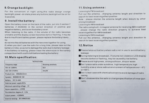
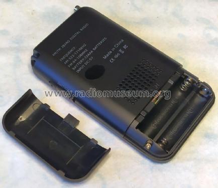
- Batterie / presa di alimentazione supplementare / AAA: 2 x 1.5 / DC IN 5 Volt
- Altoparlante
- AP magnetodinamico (magnete permanente e bobina mobile) / Ø 4 cm = 1.6 inch
- Potenza d'uscita
- 0.2 W (indistorta)
- Materiali
- Plastica (non bachelite o catalina)
- Radiomuseum.org
- Modello: FM/AM 2-Band Digital radio HRD-104 - Hanrongda Electronic Co. Ltd.;
- Forma
- Tascabile (portatile molto piccola), < 20 cm
- Dimensioni (LxAxP)
- 60 x 100 x 15 mm / 2.4 x 3.9 x 0.6 inch
- Annotazioni
-
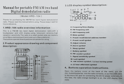
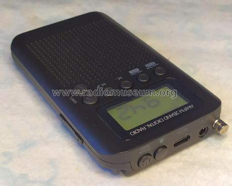
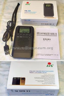
The HanRongDa HRD-104 pocket radio features AM and FM bands, clock, alarm and sleep timer.
Main features
- FM: 64 - 108 MHz
- Sensitivity: 8 uV
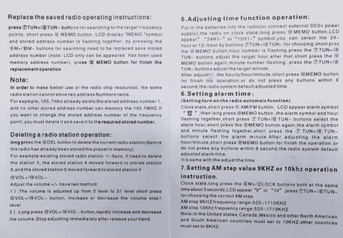
- AM: 522 - 1710 kHz (9 kHz steps), 520 - 1710 kHz (10 kHz steps), selectable
- Sensitivity: 3mV/m
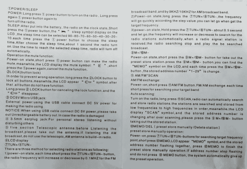
- Manual and Automatic tuning
- 56 Memory pressets
- USB port for a 5 VDC external power adapter
- 3.5 mm jack for stereo earphones (recommended 32 Ohm)
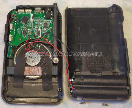
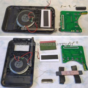
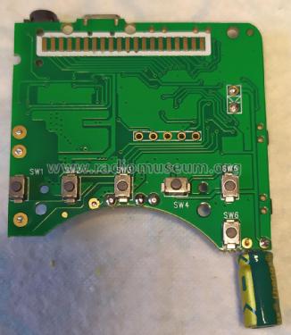
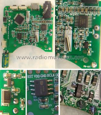
Brief technical details
There are at least two chassis versions, featuring two different designs.
One of them has the PCB with reference "HRD-104B-6958" and uses the AKC6958 DSP chip (IC1) managed by a MC96F6408AL MCU chip.(IC2).
The other one covered here has a PCB with reference "HRD-104B 1.0MM-FR4 2022-10-26".
The design is based around a KT0913L-D4 AM/FM DSP, stereo, with integrated earphones driver, IC (U1). The FM antenna signal is shaped by a RF front-end using a 2SC3356-R25 NPN transistor (Q1). The built-in speaker is driven by a 8002B 2W Class-AB single channel audio amplifier configured in BTL mode, IC (U4).
The MCU IC (U2) is unmarked.
The power supply uses a 65Z5 (XC6206P302MR) 3.0V LDO regulator to bring the USB 5V down to acceptable operating levels. A Y2 (SS8550) PNP transistor (Q2) acts as a power switch managed by the MCU. (U2).
- FM: 64 - 108 MHz
- Autore
- Modello inviato da Jose Mesquita. Utilizzare "Proponi modifica" per inviare ulteriori dati.
- Altri modelli
-
In questo link sono elencati 5 modelli, di cui 5 con immagini e 5 con schemi.
Elenco delle radio e altri apparecchi della Hanrongda Electronic Co. Ltd.; Shenzhen
Collezioni
Il modello FM/AM 2-Band Digital radio fa parte delle collezioni dei seguenti membri.