FM/AM 2-Band Digital radio HRD-104
Hanrongda Electronic Co. Ltd.; Shenzhen
- Fabricant / Marque
- Hanrongda Electronic Co. Ltd.; Shenzhen
- Année
- 2019 ?
- Catégorie
- Radio - ou tuner d'après la guerre 1939-45
- Radiomuseum.org ID
- 349686

Cliquez sur la vignette du schéma pour le demander en tant que document gratuit.
- No. de transistors
- 2
- Semi-conducteurs
- Principe général
- DSP, traitement numérique du signal
- Gammes d'ondes
- PO et FM
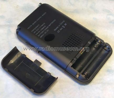
- Tension / type courant
- Batteries / Alim. BT séparée avec fiche / AAA: 2 x 1.5 / DC IN 5 Volt
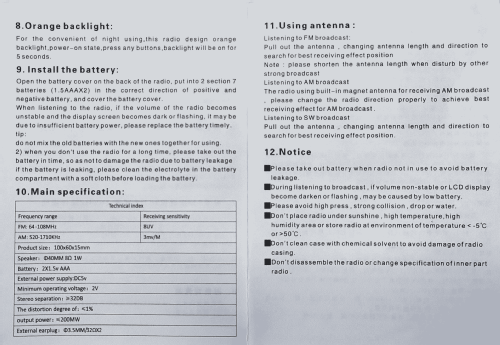
- Haut-parleur
- HP dynamique à aimant permanent + bobine mobile / Ø 4 cm = 1.6 inch
- Puissance de sortie
- 0.2 W (sans distorsion)
- Matière
- Plastique moderne (pas de bakélite, ni de catalin)
- De Radiomuseum.org
- Modèle: FM/AM 2-Band Digital radio HRD-104 - Hanrongda Electronic Co. Ltd.;
- Forme
- Portable, appareil de poche. Taille < 20cm
- Dimensions (LHP)
- 60 x 100 x 15 mm / 2.4 x 3.9 x 0.6 inch
- Remarques
-
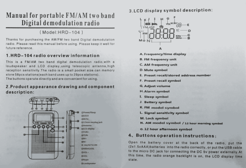
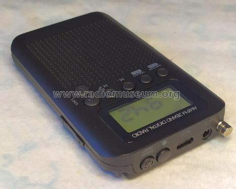
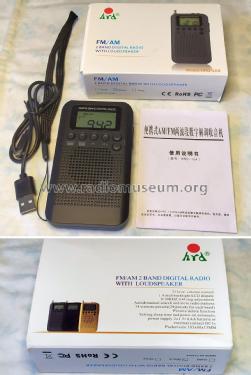
The HanRongDa HRD-104 pocket radio features AM and FM bands, clock, alarm and sleep timer.
Main features
- FM: 64 - 108 MHz
- Sensitivity: 8 uV
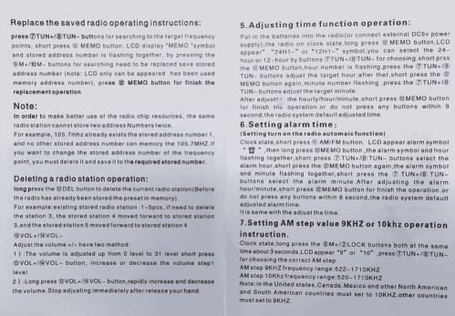
- AM: 522 - 1710 kHz (9 kHz steps), 520 - 1710 kHz (10 kHz steps), selectable
- Sensitivity: 3mV/m
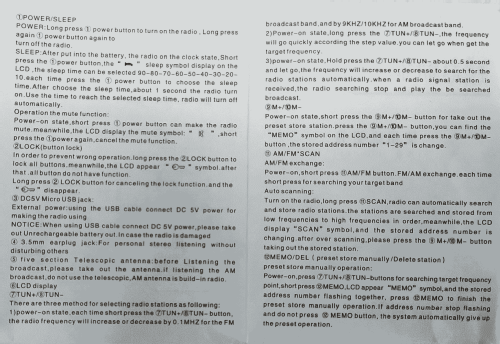
- Manual and Automatic tuning
- 56 Memory pressets
- USB port for a 5 VDC external power adapter
- 3.5 mm jack for stereo earphones (recommended 32 Ohm)
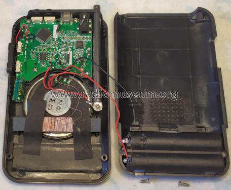
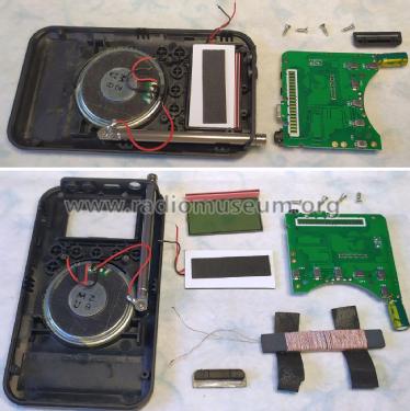
Brief technical details
There are at least two chassis versions, featuring two different designs.
One of them has the PCB with reference "HRD-104B-6958" and uses the AKC6958 DSP chip (IC1) managed by a MC96F6408AL MCU chip.(IC2).
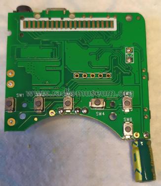
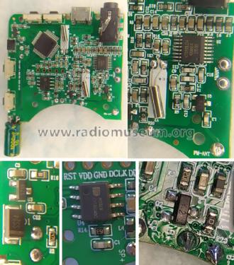
The other one covered here has a PCB with reference "HRD-104B 1.0MM-FR4 2022-10-26".
The design is based around a KT0913L-D4 AM/FM DSP, stereo, with integrated earphones driver, IC (U1). The FM antenna signal is shaped by a RF front-end using a 2SC3356-R25 NPN transistor (Q1). The built-in speaker is driven by a 8002B 2W Class-AB single channel audio amplifier configured in BTL mode, IC (U4).
The MCU IC (U2) is unmarked.
The power supply uses a 65Z5 (XC6206P302MR) 3.0V LDO regulator to bring the USB 5V down to acceptable operating levels. A Y2 (SS8550) PNP transistor (Q2) acts as a power switch managed by the MCU. (U2).
- FM: 64 - 108 MHz
- Auteur
- Modèle crée par Jose Mesquita. Voir les propositions de modification pour les contributeurs supplémentaires.
- D'autres Modèles
-
Vous pourrez trouver sous ce lien 5 modèles d'appareils, 5 avec des images et 5 avec des schémas.
Tous les appareils de Hanrongda Electronic Co. Ltd.; Shenzhen
Collections
Le modèle FM/AM 2-Band Digital radio fait partie des collections des membres suivants.