1 Tube, Reflex
Harkness Radio Corp.; Newark
- Country
- United States of America (USA)
- Manufacturer / Brand
- Harkness Radio Corp.; Newark
- Year
- 1924
- Category
- Broadcast Receiver - or past WW2 Tuner
- Radiomuseum.org ID
- 331571
Click on the schematic thumbnail to request the schematic as a free document.
- Number of Tubes
- 1
- Valves / Tubes
- Main principle
- TRF without regeneration; Reflex
- Wave bands
- Broadcast only (MW).
- Power type and voltage
- Batteries / addl. power jack
- Loudspeaker
- - This model requires external speaker(s).
- Material
- Bakelite, TUBES VISIBLE
- from Radiomuseum.org
- Model: 1 Tube, Reflex - Harkness Radio Corp.; Newark
- Notes
-
1 Tube, Reflex TRF receiver with no regeneration utilizing special tuned transformers manufactured by Harkness and sold as a home-built kit.
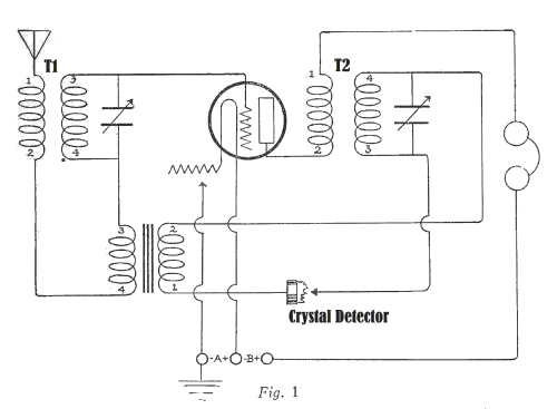
The fundamental Harkness Reflex circuit is shown in Fig. 1. The functioning of the circuit is based, of course, upon the principle of reflex amplification. The amplifying tube serves a double purpose. it amplifies the high frequency currents of incoming signals and, after rectification by the crystal, also amplifies the audio frequency current variations.The main distinctive features of this circuit are as follows:
(1) Tuned radio frequency amplification is used. T1 and T2 are special radio frequency transformers with untuned primaries and tuned secondaries. In the ordinary reflex receiver, the transformer which corresponds to T2 is untuned. Much higher radio frequency amplification is secured by tuning the secondary of this transformer. The selectivity is also greatly increased.
(2) The grid of the reflex amplifying tube is connected (through the secondary of the audio frequency transformer) to the negative side of the filament circuit. This ensures maximum audio frequency amplification. In previous types of reflex receivers, it was found necessary to connect the grid return to the sliding contact of a potentiometer shunted across the filament circuit, in order that self -oscillation could be controlled. This method of controlling self-oscillation, however, greatly diminishes the audio frequency amplification of a reflex system. In fact, if, by moving the sliding contact of the potentiometer, the grid is given a positive potential with respect to the negative side of the filament, the audio frequency amplification is practically reduced to zero. This can easily be proven by reversing the filament battery leads of any audio frequency amplifier. When the grids of the amplifying tubes are connected to the positive sides of the filament the audio frequency amplification disappears. In the Harkness reflex circuit, however. the grid of the tube remains permanently connected to the negative side of the filament.
(3) The Harkness Reflex does not use a potentiometer, neutralizing condenser, or any of the other known methods of controlling self-oscillation. Nevertheless, the receiver does not oscillate.The reason for this lies, particularly, in the design of the radio frequency transformers. The impedance of transformer T2 is arranged so that the oscillations set up across the primary of this transformer do not feedback sufficient energy through the capacity of the tube to generate continuous oscillations. A detailed explanation of this feature of the circuit is the subject of an article, Radio in the Home June 1924, pages 10 & 11.
- Mentioned in
- -- Original prospect or advert (Radio in the Home June 1924, pages 10 & 11)
- Author
- Model page created by Gary Cowans. See "Data change" for further contributors.
- Other Models
-
Here you find 7 models, 6 with images and 4 with schematics for wireless sets etc. In French: TSF for Télégraphie sans fil.
All listed radios etc. from Harkness Radio Corp.; Newark