1 Tube, Reflex
Harkness Radio Corp.; Newark
- Pays
- Etats-Unis
- Fabricant / Marque
- Harkness Radio Corp.; Newark
- Année
- 1924
- Catégorie
- Radio - ou tuner d'après la guerre 1939-45
- Radiomuseum.org ID
- 331571
Cliquez sur la vignette du schéma pour le demander en tant que document gratuit.
- No. de tubes
- 1
- Lampes / Tubes
- Principe général
- Récepteur TRF - sans réaction (pas régénératif); Reflex
- Gammes d'ondes
- PO uniquement
- Tension / type courant
- Batteries / Alim. BT séparée avec fiche
- Haut-parleur
- - Ce modèle nécessite des HP externes
- Matière
- Boitier en bakélite, lampes visibles
- De Radiomuseum.org
- Modèle: 1 Tube, Reflex - Harkness Radio Corp.; Newark
- Remarques
-
1 Tube, Reflex TRF receiver with no regeneration utilizing special tuned transformers manufactured by Harkness and sold as a home-built kit.
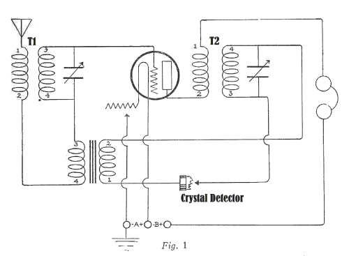
The fundamental Harkness Reflex circuit is shown in Fig. 1. The functioning of the circuit is based, of course, upon the principle of reflex amplification. The amplifying tube serves a double purpose. it amplifies the high frequency currents of incoming signals and, after rectification by the crystal, also amplifies the audio frequency current variations.The main distinctive features of this circuit are as follows:
(1) Tuned radio frequency amplification is used. T1 and T2 are special radio frequency transformers with untuned primaries and tuned secondaries. In the ordinary reflex receiver, the transformer which corresponds to T2 is untuned. Much higher radio frequency amplification is secured by tuning the secondary of this transformer. The selectivity is also greatly increased.
(2) The grid of the reflex amplifying tube is connected (through the secondary of the audio frequency transformer) to the negative side of the filament circuit. This ensures maximum audio frequency amplification. In previous types of reflex receivers, it was found necessary to connect the grid return to the sliding contact of a potentiometer shunted across the filament circuit, in order that self -oscillation could be controlled. This method of controlling self-oscillation, however, greatly diminishes the audio frequency amplification of a reflex system. In fact, if, by moving the sliding contact of the potentiometer, the grid is given a positive potential with respect to the negative side of the filament, the audio frequency amplification is practically reduced to zero. This can easily be proven by reversing the filament battery leads of any audio frequency amplifier. When the grids of the amplifying tubes are connected to the positive sides of the filament the audio frequency amplification disappears. In the Harkness reflex circuit, however. the grid of the tube remains permanently connected to the negative side of the filament.
(3) The Harkness Reflex does not use a potentiometer, neutralizing condenser, or any of the other known methods of controlling self-oscillation. Nevertheless, the receiver does not oscillate.The reason for this lies, particularly, in the design of the radio frequency transformers. The impedance of transformer T2 is arranged so that the oscillations set up across the primary of this transformer do not feedback sufficient energy through the capacity of the tube to generate continuous oscillations. A detailed explanation of this feature of the circuit is the subject of an article, Radio in the Home June 1924, pages 10 & 11.
- Littérature
- -- Original prospect or advert (Radio in the Home June 1924, pages 10 & 11)
- Auteur
- Modèle crée par Gary Cowans. Voir les propositions de modification pour les contributeurs supplémentaires.
- D'autres Modèles
-
Vous pourrez trouver sous ce lien 7 modèles d'appareils, 6 avec des images et 4 avec des schémas.
Tous les appareils de Harkness Radio Corp.; Newark