Counterflex 3 late UX types
Harkness Radio Corp.; Newark
- Land
- USA
- Hersteller / Marke
- Harkness Radio Corp.; Newark
- Jahr
- 1925

- Kategorie
- Rundfunkempfänger (Radio - oder Tuner nach WW2)
- Radiomuseum.org ID
- 44116
Ebay Nr. 160131276884 Bild bearbeitet.
Ebay Nr. 160131276884 Bild bearbeitet.

Ebay Nr. 160131276884 Bild bearbeitet.
Ebay Nr. 160131276884 Bild bearbeitet.
Ebay Nr. 160131276884 Bild bearbeitet.
Klicken Sie auf den Schaltplanausschnitt, um diesen kostenlos als Dokument anzufordern.
- Anzahl Röhren
- 3
- Hauptprinzip
- Geradeaus ohne Rückkopplung; Reflex
- Anzahl Kreise
- 2 Kreis(e) AM
- Wellenbereiche
- Mittelwelle, keine anderen.
- Betriebsart / Volt
- Akku und/oder Batterie
- Lautsprecher
- - Dieses Modell benötigt externe(n) Lautsprecher.
- Material
- Gerät mit Holzgehäuse
- von Radiomuseum.org
- Modell: Counterflex 3 [late UX types] - Harkness Radio Corp.; Newark
- Form
- Tischmodell, Zusatz nicht bekannt - allgemein.
- Bemerkung
-
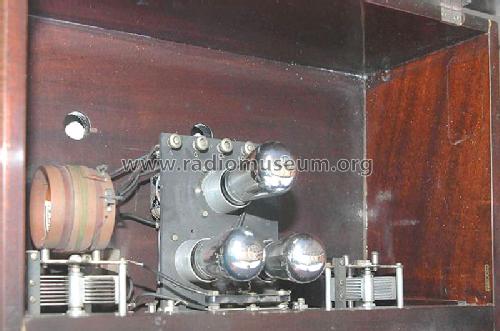
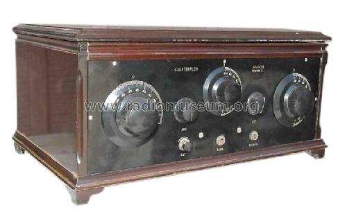
The Harkness 3 tube receiver is a Reflex circuit that employs tuned radio frequency amplification without the necessity of using a potentiometer or neutralizing condensers to prevent self-oscillation.
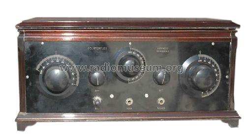
The set has only two dial controls, and when the best positions of these have been found for various stations, the positions can be permanently logged for future reference.See the first 3 tubes Counterfiex receiver in this link. It is primarily intended for use with UV201A or UV301A tubes. With these tubes a 6-volt filament battery and a 90-volt plate battery are required, the plate battery being tapped at 22½ volts for the detector-tube plate circuit. It is possible. of course, to use dry cell tubes, but it is then usually necessary to change the capacity of the fixed condenser across the secondary of the reflex audio-frequency transformer.
A slightly larger capacity than that shown in the diagram is needed. The exact capacity can best be found by experiment.
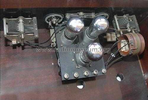
The same types of tubes must be used throughout; that is to say, use three UV201A's or three UV199's or three UV112's (112, 12). Do not use two UV201A and one UV200. If you want to use a UV200 as a detector you must change the wiring of the filament circuit and insert a separate rheostat to control the filament current of the detector tube. Radio in the Home, October 1924, page 37.But this model here is in late 1925 with UX201A tubes - please look up the base UV or UX when you place photos.
See Forum Article from Radio in the Home below for a technical and construction description by Kenneth Harkness.
- Originalpreis
- 36.00 $
- Datenherkunft extern
- Ernst Erb
- Datenherkunft
- Radio Collector`s Guide 1921-1932
- Literatur/Schema (1)
- -- Original prospect or advert (Radio in the Home October 1924, Pages 11 –13, 27, 44)
- Weitere Modelle
-
Hier finden Sie 7 Modelle, davon 6 mit Bildern und 4 mit Schaltbildern.
Alle gelisteten Radios usw. von Harkness Radio Corp.; Newark
Forumsbeiträge zum Modell: Harkness Radio Corp.: Counterflex 3
Threads: 1 | Posts: 1
Radio in the Home October 1924, Pages 11 –13, 27, 44
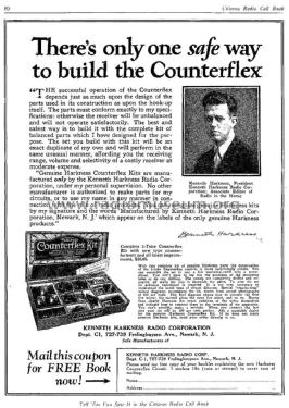
The New Harkness Counterflex Circuit
 By Kenneth Harkness
President, Kenneth Harkness Radio Corporation
I am glad to be able to give readers of Radio in the Home the first details of a new circuit which I have recently perfected. As a matter of fact, it is more than just a "circuit"; it is a new method of controlling self-oscillation in a reflex receiver, a method which can be used in various reflex circuits, and which enables the construction of unusually efficient reflex receivers. Receivers using this new method of controlling self -oscillation will be known as "Counterflex" receivers.
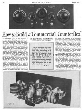
In this issue I am showing the circuit and photographs of a three tube Counterflex receiver which I believe to be one of the simplest and best applications of the Counterflex principle. This receiver is remarkably efficient. In both audibility and selectivity, it has proved to be the equal of a popular type of five tube set.
For instance, at Station 3XP, where I demonstrated the set one hot evening in August when static was at its worst and receiving conditions were distinctly unfavourable, we were able easily to pick up stations within a radius of about 1000 miles with more than sufficient audibility to operate a loudspeaker satisfactorily. It was the general opinion of those who were present at this demonstration that the Counterflex had "some kick to it." I have also tested the receiver in other localities, and it has invariably proved itself to be equally efficient.
As stated above, the important new feature of the Counterflex circuit is the method used to control self- oscillation. In the July issue of this magazine. I discussed the subject of self-oscillation in some detail, explaining the causes responsible for this effect, the precautions which must be taken to minimize these causes and the means which may be adopted to control self- oscillation when it is impossible, by precautionary measures alone, to prevent self-oscillation from taking place. I explained that self-oscillation in a receiver with radio frequency amplification is caused by inductive or capacitive coupling between the circuits of the amplifier. This coupling cannot be entirely eliminated as some of it is inherent in the amplifier; for instance, the coupling caused by the capacity between the plate and grid of each vacuum tube is inherent and cannot be avoided. It is necessary, therefore, to add resistance to the circuits in some convenient manner so as to prevent the generation of continuous oscillations.
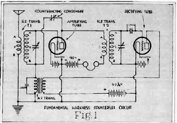
In the Counterflex circuit, self-oscillation is controlled by coupling the circuits of the radio frequency amplifier to produce a negative feed -back effect, a feed -back which is directly "out of phase" with the positive feedback set up by the inherent coupling between the circuits.Whereas the positive feedback decreases the effective resistance of the circuits, and, if it is strong enough, permits the generation of continuous oscillations, the negative feed -back increases the effective resistance of the circuits and prevents the generation of continuous oscillations. The positive feedback has an amplifying effect, known as regeneration or reaction; the negative feedback has a diminishing effect which I have termed counteraction. The underlying principle of this system of controlling self -oscillation is commonly called "neutralization," although it seems to me that the term "counteraction" better describes the action which takes place. The principle is not new, having been clearly set forth by French engineers about ten years ago, but the method of applying the counteraction principle in the Counterflex receiver is entirely new and original and has many advantages over other methods. The fundamental Counterflex circuit is shown in the diagram of Figure 1. In this diagram separate batteries are shown for each tube so that the essential connections of the circuit may he more clearly seen. If this diagram is studied, it will be seen that the circuit is very similar to the "Harkness Reflex" circuit, except that a vacuum tube is used as a rectifier in place of a crystal detector. The amplifying tube serves a double purpose. It amplifies the high -frequency currents of incoming signals, and, after rectification by the detector tube, also amplifies the audio -frequency current variations, the signals finally being detected by the telephones included in the plate circuit of the amplifying tube.
The radio -frequency transformers T1 and T2 are similar to the transformers T1 and T2 of the Harkness Reflex, although the inductance values are different. To ensure maximum sensitiveness the terminals of these transformers must be correctly connected in the circuit. In Figure 1 the letters A and B represent, respectively, the beginning and end of each winding, the primary and secondary coils of each transformer being wound in the same direction. Now, the inductance values of the radio - frequency transformers are such that continuous oscillations would he self- generated in this circuit if no means were provided to control self-oscillation. Counteraction, therefore, is used for this purpose, and it is obtained by connecting a small variable condenser between the plate of the amplifying tube and the filament ride of the secondary coil of radio -frequency transformer T2. This method of obtaining and varying counteraction to control self -oscillation in a reflex circuit is entirely new. it is positive in action and permits a simple and accurate control of counteraction. Counteraction can be increased or decreased, as may be necessary, by increasing or decreasing the capacity of the counteracting condenser. If, while tuning in signals, continuous oscillations are generated by the amplifying tube they can he promptly and accurately dampened out by increasing the capacity of the counteracting condenser. The exact value of counteraction necessary for maximum efficiency at any frequency to which the receiver may be tuned can easily be obtained. The use of this method of obtaining and varying counteraction enables the construction of highly efficient reflex receivers based upon the fundamental circuit of Figure 1. The inductance values of the radio frequency transformers (particularly T2) can he sufficiently high to obtain un- usually good radio- frequency amplification. In place of the crystal detector of the Harkness Reflex system a vacuum tube can be used for rectification, thus simplifying the operation, and greatly increasing the selectivity of the receiver. The normal potential of the grid of the amplifying tube can be maintained at a negative value, thus insuring maximum audio- frequency amplification.

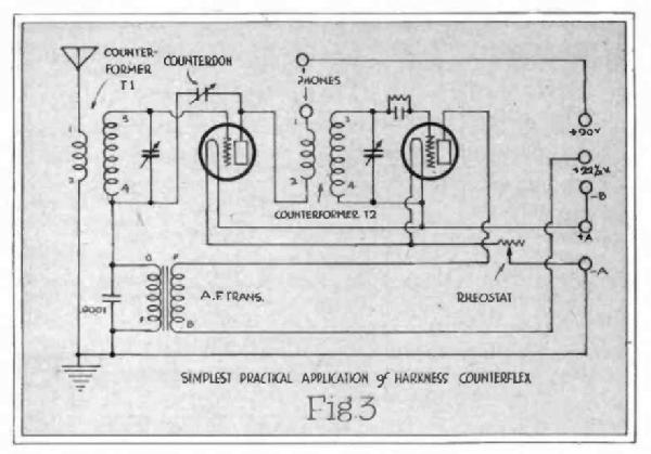
The diagram of Figure 3 illustrates the simplest practical application of the Counterfiex circuit. For all around service it is better to use a third tube as audio frequency amplifier, the two-tube circuit of Figure 3 being intended for use with headphones only. The two-tube circuit, however, will operate a loudspeaker when with low minimum capacity are as follows:
Transformer T1: Secondary coil has sixty turns of No. 28 silk covered wire wound on a formica form 2⅝ inches in diameter. Primary coil has ten turns of the same size of wire wound directly on top of the secondary coil, the two coils being separated by a piece of insulating paper or Empire cloth. Roth coils are wound in the same direction.
Transformer T2: Secondary coil has fifty -five turns of No. 28 silk -covered wire wound on a formica form 2⅝ inches in diameter. Primary coil has twenty-five turns of the same size wire. The coils are wound in the same manner as type T1.
These transformers, mounted on the variable condensers for which they are designed, may be purchased, if desired. The complete transformer and variable condenser unit will be placed on the market shortly and will be known as the "Harkness Counterformer." These units are similar to the Flexoformer of the old Harkness Reflex circuit except that the constants of the coils are different. The counterformers will be obtainable, of course, in two types (TI and T2) as required by the circuit.There is nothing particularly unusual about the counteracting condenser of the Counterflex circuit. It is merely a small variable condenser. It is possible to use some of the standard types of "vernier" condensers now on the market, although I am designing a special condenser with the correct range of capacity needed by the circuit. This special condenser will be known as the "Harkness Counterdon."
Using the above-described special parts and other standard material the two-tube circuit of Figure 3, then, can be built with the following items:
1 Counterformer Type T1.
1 Counterformer Type T2.
1 Audio -frequency transformer.(ratio 4 to 1).
1 Counterdon or "vernier" condenser.
1 Filament rheostat.
1 Grid condenser (.00025) and grid leak (1 meg.).
1 Fixed condenser (.0001 mf.).
2 Tube sockets.
8 Binding posts.
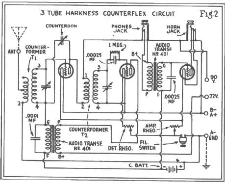
The counterformers, counterdon and rheostat should be mounted on a front panel measuring 7 inches by 18 inches and the remainder of the parts screwed to a baseboard, the binding posts preferably being mounted on a strip at the back of the base board. The parts can then be wired up as shown in Figure 3. The terminals of the counterformers are numbered, and it is absolutely essential that the connections he made to these terminals to correspond with the diagram of Figure 3. On Counterformer T1 terminal No. 1 is the beginning of the primary winding and terminal No. 3 the beginning of the secondary winding. On counterformer T2 terminal No. 1 is the beginning of the primary coil and terminal No. 4 the beginning of the secondary. With an additional stage o4 audio -frequency amplification the Counterflex receiver becomes a much more serviceable instrument. For headphone reception the telephones can be plugged in the plate circuit of the reflex tube, thus cutting out the third tube entirely, or the loud speaker can be plugged in the plate circuit of the audio frequency amplifying tube for the reception of both local and distant stations with goodvolume.
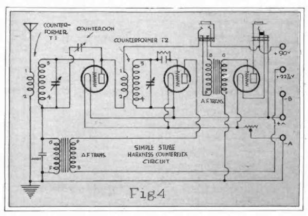

I show, in Figures 4 and 5, two different circuits, each using three tubes.
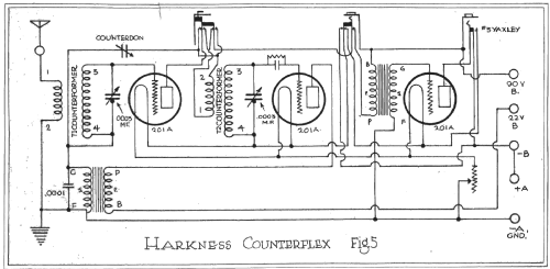
Figure 5 is the circuit which will be used in the commercial model of three-tube Harkness Counterflex receiver. Figure 4 is a modified and simpler arrangement of the same circuit. It will be noticed that the commercial circuit of Figure 5 uses a special "counterswitch," while the circuit of Figure 4 omits this entirely. Otherwise, the circuits are identical, with the minor exception of the fact that both jacks of the commercial circuit are of the filament control type, whereas the simpler circuit has an ordinary double circuit jack in the plate circuit of the reflex amplifying tube. The "counterswitch" of Figure 5 is merely a special type of double -pole, double - throw switch. If the wiring diagram is studied, it will be seen that this switch makes it possible to reverse the connections of the primary coil of counterformer T2. The object of this switch is to prevent the receiver from "squealing" when the strong signals of nearby broadcasting stations set up forced oscillations which cannot be controlled by the counterdon.
If you live more than twenty -five miles from a broadcasting station, you will not need to use this switch at all; you can then permanently connect counterformer T2 as shown in Figure 4, the beginning of the primary coil going to the plate of the reflex tube, and the beginning of the secondary coil going to the grid of the detector tube. But if you live within two or three miles of a broadcasting station, the strong signals from this station will cause the receiver to howl when the station is tuned in. It is possible, of course, to eliminate this howl by detuning the set, but this use of the counterswitch renders this unnecessary and makes it easier to pick up different local stations. Incidentally, with the counter - switch on the "local" side, the audibility of the receiver is so greatly reduced that the receiver is more selective, and the different local station can be received without interference. The three-tube Counterflex circuit of Figure 5 can be built with the following parts:
1 Counterformer Type T1.
1 Counterformer Type T2.
2 Audio-frequency transformers.
1 Counterdon.
1 Counterswitch.
3 Tube sockets.
1 Double-circuit fil. control jack
1 Single-circuit fil. control jack
1 Filament rheostat
1 Fixed condenser (.0001 mfd.).
1 Grid condenser (.00025 mf) and grid leak (1 megohm).
6 Binding posts.
The counterformers. counterdon, counterswitch, filament rheostat and telephone jacks can be mounted on a panel measuring 7 inches by 18 inches and the remainder of the parts on a baseboard. the various parts being connected together as shown in the wiring diagram.
A receiver using the circuit of Figure 4 can be built using exactly the same parts as listed above, omitting, however, the counterswitch and substituting an ordinary double-circuit jack for the double-circuit filament control jack. The Counterfiex receiver is primarily intended for use with 201A or 301A tubes. With these tubes a 6-volt filament battery and 90 -volt plate battery are required, the plate battery being tapped at 22½ volts for the detector-tube plate circuit. It is possible. of course, to use dry cell tubes, but it is then usually necessary to change the capacity of the fixed condenser across the secondary of the reflex audio -frequency transformer. A slightly larger capacity than that shown in the diagram is needed. The exact capacity can best be found by experiment. The same types of tubes must be used throughout; that is to say, use three 201A's or three 199's or three 12's. Do not use two 201 A and one UV200. If you want to use a 200 as detector you must change the wiring of the filament circuit and insert a separate rheostat to control the filament current of the detector tube.
There is a very simple and infallible test for determining whether your Counterflex receiver is operating with maximum efficiency. Be sure to make this test and correct any mistake it reveals before calling your set "perfect."
To make this test. choose a time when local stations are not broadcasting. Connect your antenna. Ground and batteries and plug in your phones or loudspeaker. Turn the counter - switch to the "distant" side and turn the counterdon to the minimum position (rotor plates out). Then, provided the secondaries of the two counterformers are tuned to the same frequency, a howl should be heard in the telephones or loud speaker, no matter to what frequency both circuits are tuned. In other words, if by turning the first dial to 10 degrees the circuit is tuned to a wavelength of about 220 meters, a howl should be heard in the phones when the second dial is turned to approximately the same position as the first. There may be a slight difference between the settings of the two dials; for instance, to obtain 220 meters on the second dial 12 degrees may be the correct position. Similarly, if the first dial is turned to 70 degrees, representing, say, the correct position for the reception of 500 meter waves, a howl should be heard when the second dial is tuned to 500 meters.Furthermore, it should he possible completely to eliminate this howl by increasing the capacity of the counteracting condenser. or counterdon, no matter what frequency the two circuits may be tuned to.
When making this test you may find:
(1) That while you are able to stop howling at all frequencies by turning the counterdon, the receiver driest not hotel at all at some frequencies.
The cause of this may be the length of your aerial. If it is longer than 60 feet, cut it down to that length. If this does not balance up your receiver the values of some of the parts you are using may be incorrect. This can be remedied by using the correct parts or, in some cases, by increasing the capacity of the fixed condenser across the secondary of the reflex audio-frequency transformer. The correct capacity can be found by experiment.
On the other hand, you may find:
(2) That while the receiver howls at all frequencies, you are unable to stop the howl at some particular frequencies. Again, the cause for this may be the length of your aerial. If it is too short, increase it to about 60 feet.
Or the cause may be the use of incorrectly designed parts which can be remedied by substituting the correct parts or, in some cases. by decreasing the capacity of the fixed condenser across the secondary of the reflex audio-frequency transformer. The correct capacity can he found by experiment.
There are two methods of operating the Counterflex receiver. Both are simple, but the first method is absolutely foolproof, viz.:
(1) After the manner of the neutrodyne receiver, adjust the counterdon so that it is impossible to make the receiver howl, no matter what the frequency to which the two circuits may be tuned. The counterdon can then be left permanently in this position and different stations tuned in by merely revolving the two tuning dials.
(2) After tuning in a station by means of the tuning dials, accurately adjust the counterdon so that the correct amount of counteraction is obtained to insure maximum sensitiveness for the reception of the particular frequency to which the circuits are tuned.
The second method is, of course, the preferable one as the receiver can be brought to the state of maximum sensitiveness by controlling counteraction. I am particularly anxious to hear from the readers of this magazine of the results they obtain with this new circuit. Let me know how it compares with other receivers you own or have built. I think you are going to be somewhat amazed by the ease with which you are able to pick up distant stations with this system. I am inclined to be conservative in making claims for any circuit, but I have no hesitation in saying that I have yet to find the three-tube receiver which can approach the three-tube Counterflex for sensitiveness, selectivity, and ease of operation. If you have any questions to ask, please do not hesitate to write me. I only ask that you tabulate your questions and make them as clear as possible. If I am unable to answer all questions individually, I will answer them en masse in a future issue of Radio in the Home.
Gary Cowans, 09.Aug.21