- País
- Estados Unidos
- Fabricante / Marca
- Harkness Radio Corp.; Newark
- Año
- 1926
- Categoría
- Radio - o Sintonizador pasado WW2
- Radiomuseum.org ID
- 44118

Haga clic en la miniatura esquemática para solicitarlo como documento gratuito.
- Numero de valvulas
- 6
- Principio principal
- RFS sin reacción
- Gama de ondas
- OM (onda media) solamente
- Tensión de funcionamiento
- Baterías recargables o pilas / 5 & 90 & 135 Volt
- Altavoz
- - Este modelo usa altavoz exterior (1 o más).
- Material
- Madera
- de Radiomuseum.org
- Modelo: KH-27 - Harkness Radio Corp.; Newark
- Forma
- Sobremesa, caja, normalmente con tapa (panel no inclinado).
- Anotaciones
-
Six tube TRF receiver using two as RF amplifiers, one as a detector, and three as audio amplifiers.
This receiver featured an entirely new type of audio frequency amplification, the Hiler double- impedance system. It was designed by Kenneth Harkness to attain the best possible tone quality as well as to meet high requirements for volume and selectivity.Cost of parts in 1927: Not more than $86.50
- Precio durante el primer año
- 86.50 USD
- Ext. procedencia de los datos
- Ernst Erb
- Procedencia de los datos
- Radio Collector`s Guide 1921-1932
- Mencionado en
- -- Original prospect or advert (Popular Radio, January 1927, Pages 17-20 & 68.)
- Otros modelos
-
Donde encontrará 7 modelos, 6 con imágenes y 4 con esquemas.
Ir al listado general de Harkness Radio Corp.; Newark
Contribuciones en el Foro acerca de este modelo: Harkness Radio Corp.: KH-27
Hilos: 1 | Mensajes: 1
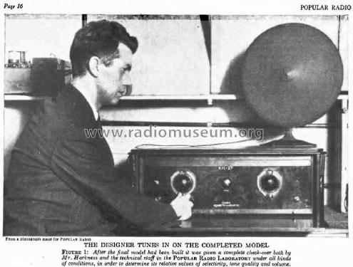
Popular Radio, January 1927, Pages 17-20 & 68.
DESCRIPTION OF THE NEW KH -27 RECEIVER
By KENNETH HARKNESS
THE KH-27 is the result of a long series of experiments conducted by the writer during the summer of 1926.
The primary object of these experiments was the development of a receiver with perfect tone quality; all other characteristics were made subservient. However, in so doing, nothing was omitted of the essential characteristics of a good receiving set.
In addition, therefore, to its remarkable tone quality the KH-27 has the following desirable features:
1. It is an exceptionally good "distance-getter."
2. The selectivity is adequate for all purposes; even in districts surrounded by broadcasting stations the set will receive any desired station without interference from other stations.
3. The set is easy to operate; only two tuning dials are used.
4. It is entirely non-regenerative as it is neutralized to prevent oscillation. The set does not whistle, or squeal and it cannot radiate.
5. Any type of outdoor or indoor antenna may be used with it; local stations can be received without any antenna if desired.
6. The set will operate with ordinary "A" and "B" batteries or on the house current by the use of power packs.
7. Standard parts, easily obtainable, are used in the construction of the set.
The front and sub-panels are of standard size and any desired type of cabinet may be purchased to accommodate the set. The set is easy to build and once it is installed will give consistently good performance without any special care or attention.
The KH -27 should satisfy all the cravings of the DX fans. The set has two stages of radio-frequency amplification, and each stage gives a good solid boost to an incoming signal from the broadcasting station.
The radio-frequency transformers are unusually efficient. They are space-wound on an extremely thin film of dielectric material and losses are almost too low to be measured. The primary of each transformer is wound with fifteen turns of wire and is closely coupled to the secondary. Consequently, the amplification per stage is very high.
The primary of the first radio-frequency transformer, connected in series with the antenna, is tapped at the eighth turn to permit efficient reception of short waves with the average antenna. A switch on the front panel enables the operator to connect eight or fifteen turns in series with the antenna as desired.
The large primaries of the radio frequency transformers ensure high amplification and good distance reception, but they also have another important effect; they ensure good tone quality by preventing sideband distortion in the radio-frequency amplifier. Transformers with small primaries of five or six turns not only give meagre amplification but tune altogether too sharply and thus distort the incoming signals. Each tuned circuit of the new receiver, considered by itself, tunes broadly enough to respond to frequencies about 12 kilocycles above and below the carrier frequency. To obtain good quality this is essential. But when the three circuits are tuned alike, interfering signals on frequencies outside the spectrum to which the set is adjusted are sifted out by the successive stages and do not reach the detector tube. Consequently, no interference from stations on adjoining wavelengths is experienced. In New York, within half a mile of WEAF and surrounded by about fifty other nearby stations, the set is capable of reproducing any of these stations without interference and can even bring in distant stations while the locals are on the air.
As mentioned above, the set is nonregenerative. Each stage of the radiofrequency amplifier is neutralized to prevent self-oscillation and to eliminate regeneration. The system of neutralization used in the set was developed by the writer and is an improved application of the Rice method. The scheme of connections is depicted in the wiring diagram, Figure 6.
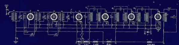 THE SCHEMATIC CIRCUIT DIAGRAM
FIGURE 6: This gives the complete hook-up at a glance. Notice that two stages of radio-frequency amplification neutralized.by an easily balanced method, a vacuum -tube detector and three stages of the new double -impedance amplification are used as well as an output filter for the last tube and loudspeaker.
Neutralization is effected by adjusting two, small, variable condensers. The large capacity of each of these condensers (.0001 mfd.) makes it easy to neutralize the set. The coils Ll and L2 are also part of the neutralizing system. These coils are placed inside of the radio: frequency transformers.
Before describing the construction of the set a brief explanation will be given of the special system of audio-frequency amplification used. The system is known as "double- impedance" audio amplification and is the invention of E. E. Hiler. The use of this system is largely responsible for the remarkable tone quality of the KH -27. The principles underlying the operation of the double-impedance, audio amplifier are easily understood. The amplifier is similar to the standard "impedance-coupled" amplifier except that choke coils are used as grid-leaks instead of the usual high resistances. This difference is responsible for the many important advantages of the system.
Practically uniform amplification of all audio frequencies can be obtained. In this respect resistance and impedance amplifiers are practically alike. Much higher amplification is obtainable, however, with impedance coupling using standard tubes and ordinary plate voltages.
The use of choke coils as grid-leaks and effectively remedies the inherent weakness of the earlier types of impedance amplifiers. Each choke coil grid -leak offers an impedance of over one million ohms to the audio-frequency signal but the DC resistance of the choke is less than 2000 ohms and excess grid charges are immediately conveyed to the filament.
All possibility of distortion or blocking on this account is therefore eliminated. There is practically no limit to the volume that can be accommodated as far as this aspect of the system is concerned and full advantage can be taken of the amplifying characteristics of the tubes in the amplifier. The double-impedance amplifier is so perfect in this respect that almost any number of stages can be used. As many as seven stages have been employed without tube blocking taking place. It is unnecessary, however, to use more than three stages in the average receiving set.
The double-impedance, audio frequency amplifier possesses many other unusual and important characteristics which are, however, beyond the scope of this article. Another feature of the set is the output tone filter which passes the direct current to the plate of the last tube, through a choke coil, and permits only audio-frequency currents to pass through the blocking condenser and the loudspeaker windings.
Gary Cowans, 11.Aug.21