- Pays
- Etats-Unis
- Fabricant / Marque
- Heathkit (Brand), Heath Co.; Benton Harbor (MI)
- Année
- 1962 ?
- Catégorie
- Radio - ou tuner d'après la guerre 1939-45
- Radiomuseum.org ID
- 90655
-
- alternative name: Heath Company
Cliquez sur la vignette du schéma pour le demander en tant que document gratuit.
- No. de tubes
- 7
- Principe général
- Super hétérodyne (en général); FI/IF 10700 kHz; 2 Etage(s) BF
- Circuits accordés
- 11 Circuits MF (FM)
- Gammes d'ondes
- FM uniquement
- Tension / type courant
- Alimentation Courant Alternatif (CA) / 117 Volt
- Haut-parleur
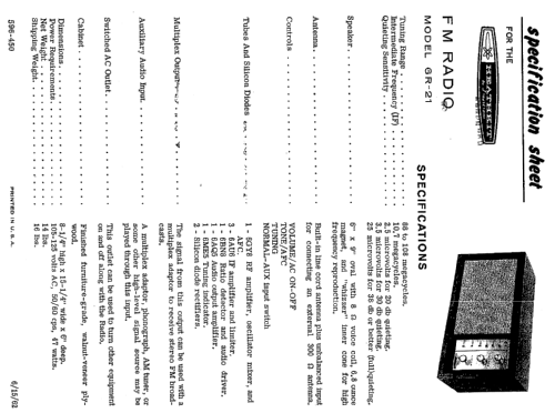
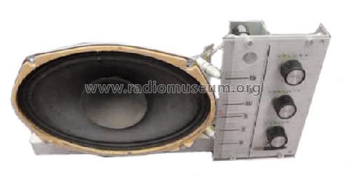
- HP dynamique oval à aimant permanent
- Matière
- Boitier en bois
- De Radiomuseum.org
- Modèle: GR-21 - Heathkit Brand, Heath Co.;
- Forme
- Modèle de table générique
- Dimensions (LHP)
- 15 x 8 x 6 inch / 381 x 203 x 152 mm
- Remarques
-
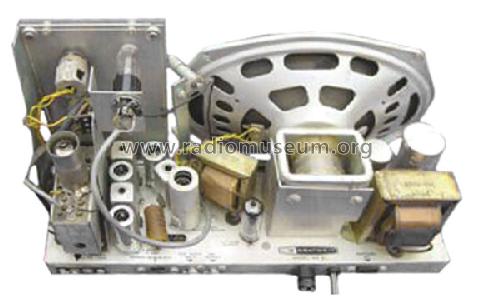
Full wave power rectification with a 2 diode voltage doubler from 142VAC HV secondary.
- Poids net
- 16 lb (16 lb 0 oz) / 7.264 kg
- Prix de mise sur le marché
- 60.00 $
- Source
- - - Manufacturers Literature
- Auteur
- Modèle crée par Hinrich Grensemann † 15.5.16. Voir les propositions de modification pour les contributeurs supplémentaires.
- D'autres Modèles
-
Vous pourrez trouver sous ce lien 720 modèles d'appareils, 703 avec des images et 507 avec des schémas.
Tous les appareils de Heathkit (Brand), Heath Co.; Benton Harbor (MI)
Contributions du forum pour ce modèle: Heathkit Brand,: GR-21
Discussions: 1 | Publications: 2
Dear Radiophiles,
This week I got a Heathkit GR-21 frrom ebay. This is an FM table radio from 1962. It has a fairly conventional American design:
-Front end triple triode 6GY8 contains the grounded grid preamp, the self-oscillating additive converter and a reactance triode for AFC. The tuning is by variable inductor.
-Three 6AU6 IF stages follow the front end.
-The first IF stage has the grid biased at DC ground via the coupling transformer.
-The second stage is an IF amplifier at low to medium input signal levels, and it becomes a limiter at the strongest stations. The limiting action is done conventionally at the input grid with a grid-leak resistor and cap (820k//270pF=>220us=>700HzBW), but the screen voltage remains high (115VDC) in either mode of operation.
-The last IF stage always functions as a limiter and is biased with a lower screen voltage (74V), which is not very low for a limiter. Like with the previous stage, limiting occurs at the grid circuit with a grid leak resistor and capacitor (100k//420pF=>42us=>4kHzBW).
-A balanced ratio detector is implemented with the dual-diode in the 6BN8. This detector seems quite stable, so it can be assumed that the detector transformer has a low enough L/C ratio to make the thermal variation of the capacitance in the thermionic diodes negligible. A large C in the tank circuit, say 50pF or larger, makes for a temperature stable detector.
-The triode in the 6BN8 and a 6AQ5 drive the large 6"x9" speaker, which has a whizer cone. The tonal quality of the amp and speaker is nice, but I added a bass boost network in parallel with the volume control input. The network is 22k in series with 5nF. Bass starts to rise below 1.5kHz, and levels off at 350Hz, with a total boost at this frequency and below, around 12dB.
-There is no explicit de-emphasis network. The tone control is expected to provide this function with variable capacitive feedback from the voice-coil to the triode cathode.
Now that I have introduced the radio, I am going to share with the trouble I found with the limting action at the second IF stage input and at the IF limiter stage input. A very good treatment of tube limiters can be found in the landmark study of the Grundig 5040W in English and German.
I did a complete aligment of this radio, which was quite laborious to get IF bandwidths that were reasonable at all levels of the input signal. Each IF stage was prone to change it's bandpass response as a function of signal level. This was true even when the signal was injected at the grid of one stage and monitored at the grid-leak RC at next stage. I removed the cathode bypass cap C22=5nF at the first IF stage to reduce the signal dependency of tuning at T1. This was sucessful and the reduction in gain was OK because plenty of gain is available from the 5 stages of RF/IF gain.
After having learned a lot reading the study of the Grundig 5040W, it makes me wish that the GR-21 Iincluded some neutralization of stray feedback capacitance, and normalization of input capacitance with unbypassed cathode resistors. But this is besides the trouble I found with the limiters of the GR-21.
Grid-leak tube limiters have a grid-leak circuit in series with the coupling transformer secondary to the grid that functions similarly to a grid-leak detector, and to the very common grounded cathode detector diodes in AM radios. If all is set up correctly, the positive peaks of the IF signal at the grid go slightly positive, with little variation. The top peaks have a flat envelope. The amplitude variations of the IF all appear nearly doubled in amplitude at the negative peaks of the IF.
It is important to note that there is no significant clipping taking place at the grid. The incomming IF may have 30% modulation on the positive peaks and 30% modulation on the negative peaks. The IF signal at the grid will have nearly 0% modulation at the positive peaks and just under 60% modulation at the negative peaks.
A common problem with this type of grounded cathode grid leak circuit is that the parallel RC (R12//C24 or R14//C20) that is in series with the coupling transformer and the grid, may be too slow to follow the troughs in the envelope. The result is a diagonal dip into the envelope trough until the envelope grows enough again to recharge the capacitor via the diode. If the envelope was a 400Hz sinewave, you end up with a 400Hz wave that has triangle shaped positive half cycles, while the negative half cycles remain sinusoidal. This is known as diagonal distortion.
So far we have only discussed behaviour at the grid in the limiter stage. The actual limiting action happens in the anode current when the negative peaks at the grid, extend beyond the grid cut-off point of the tube. When the screen biased at a low voltage the grid cut-off point is proportionally smaller by the screen mu of the tube. The screen mu (intrinsic voltage gain) for the 6AU6 is around 30. This means that grid voltages below 74V/-30=-2.5V will cut off the anode current.
A summary of pentode limiter operation would be:
1-The grid-leak circuit pushes the positive envelope onto the negative envelope, creating an IF wave at the grid that is flat topped, with twice the modulation on the negative envelope
2-The undesired negative envelope is ignored by the anode current as long as it stays below the grid cut-off voltage, which is -2.5V for the limiter stage in the GR-21.
3-The resulting limited anode current has been double limited because it has neither a positive evenlope, nor a negative one. So a single pentode limiter limits both sides of the envelope.
----------------------------
The trouble with the limiters in the GR-21 is that they produced severe diagonal destortion at the RC grid leak networks when the Antenna signal was very strong (~1mVrms) from 3 local FM stations. So I would tune very nicely through the medium strenght stations and get distorted sound on the strongest stations. This seemed the reverse of usual FM tuner behaviour: the stronger the station, the better the limiter.
The trouble with diagonal distortion at the grid leak circuit in the limiter is that it prevents the flatening of the positive side of the envelope, because the RC circuit can't rise fast enough to keep the top of the envelope flat.
The dips at the positive peaks of the envelope happen above the -2.5V cut-off of the tube, so they are passed along to the plate current.
In my description above, I mentioned the two grid leak time constants as 220us and 42us. These are not fast enough to follow the audio envelope. This is not a problem if the signal is not too strong because the AM modulations are not very deep on a well aligned IF strip. They are aproximately under 30% if the IF -3dB bandwith is set at the +/-75kHz peak FM deviation. But for very large input signals from local stations, the grid-leak circuits just can't folow the relatively high slew rates, and diagonal distortion results. This problem is worst for stereo signals that have strong content in the 38kHz band.
My solution to the limiter problem was to empirically decrease the time constants of the two grid-leak circuits. Now I have:
820k//12pF=10us for R12//C24 at second IF amp, which limits with strong signals
100k//39pF=25us for R14//C20 at IF limiter stage.
This produced a dramatic improvement in the strong signal performance. But I added a final embelishment to control overdrive. I added a 1Meg resistor from the first grid-leak R12//C24 to the control grid of the first IF amp. I added a 0.01uF coupling cap between the secondary of T1 and the first IF grid, to serve as AGC time constant filter and also disconnect the grid bias from ground. I chose the first grid-leak circuit for AGC because it only produces the desired negative control voltage for the very strongest stations. Strong signals now produce no more than -6V of AGC at the first grid leak R12//C24. I also boosted the signal to the tuning eye with 5.1Meg from it's grid to the second grid-leak R14//C20.
The following screen shots show a simulation of grid leak detection at the limiter input. A 10.7MHz sinewave with +/-100k deviation from 10kHz audio is passed through an IF filter with approximatelly 100kHz bandwidth. The first screen shot shows that a 100pF//100k=10us grid leak RC can follow the AM envelope that the LC tank imparted to the FM wave, while the second screen shot with 1000pF//10k=100us can't follow it. The slow time constant case would produce amplitude variations in anode current when the positive envelope dipped.
-------------------------------
The primary need for limiting in a practical FM radio is to eliminate the inevitable spurious amplitude modulations that occur in the IF tuned transformers. In many receivers, the limiting provided by the ratio detector is enough.
Another usueful use of limiting is for the capture effect, where a stronger station nearly completely blanks out a weaker one on the same channel. For this operation to work well, the limiter must work fast, as the beat frequencies between the two stations can be on the order of the FM deviation.
------------------------------
Comments invited,
Regards,
-Joe
Joe Sousa, 26.Jul.09


