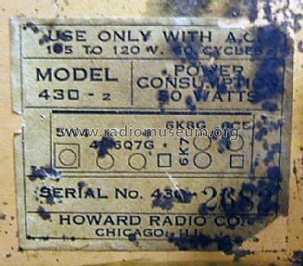
430-2 Series 2
Howard Radio Company; Chicago, IL
- País
- Estados Unidos
- Fabricante / Marca
- Howard Radio Company; Chicago, IL
- Año
- 1938
- Categoría
- Receptor para radioaficionados (puede incluir bandas de radiodifusión publ.)
- Radiomuseum.org ID
- 44547
Haga clic en la miniatura esquemática para solicitarlo como documento gratuito.
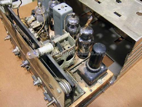
- Numero de valvulas
- 6
- Principio principal
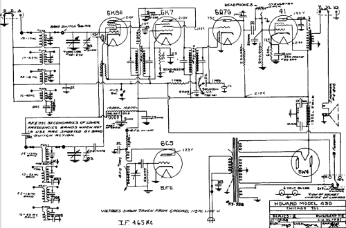
- Superheterodino en general; ZF/IF 465 kHz; 2 Etapas de AF
- Número de circuitos sintonía
- 6 Circuíto(s) AM
- Gama de ondas
- Bandas de recepción puestas en notas.
- Tensión de funcionamiento
- Red: Corriente alterna (CA, Inglés = AC) / 115 Volt
- Altavoz
- Altavoz electrodinámico (bobina de campo)
- Potencia de salida
- 1.5 W (unknown quality)
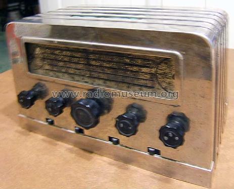
- Material
- Metálico
- de Radiomuseum.org
- Modelo: 430-2 Series 2 - Howard Radio Company; Chicago,
- Forma
- Sobremesa de tamaño mediano sin botonera <= 35 cm. (Incluso portables pero sólo con alimantación por red).
- Ancho, altura, profundidad
- 11.5 x 7.5 x 6.625 inch / 292 x 191 x 168 mm
- Anotaciones
- The original set model 430 Series 2 is housed in a metal case painted black. Only the bands acress the top and sides are painted silver. General coverage Amateur band receiver. 550 - 1700 kHz, 1700 - 5500 kHz, 5.5 - 18.0 MHz and 16.0 - 40.0 MHz bands. BFO. There are 4 switches below the control knobs: BFO-Off / On; Receive/Send (no transmitter but that the set is not damaged when transmitting with a nearby transmitter); Not sure but it should be on the schematic; Power- Off/On.
- Ext. procedencia de los datos
- James Cooke, KF5IHM, USA
- Referencia esquema
- Rider's Perpetual, Volume 10 = 1939 and before
- Otros modelos
-
Donde encontrará 354 modelos, 153 con imágenes y 214 con esquemas.
Ir al listado general de Howard Radio Company; Chicago, IL