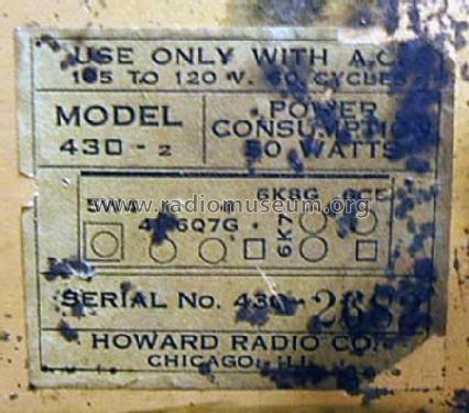
430-2 Series 2
Howard Radio Company; Chicago, IL
- Country
- United States of America (USA)
- Manufacturer / Brand
- Howard Radio Company; Chicago, IL
- Year
- 1938
- Category
- Amateur-Receiver (amateur bands, may include broadcast bands)
- Radiomuseum.org ID
- 44547
Click on the schematic thumbnail to request the schematic as a free document.
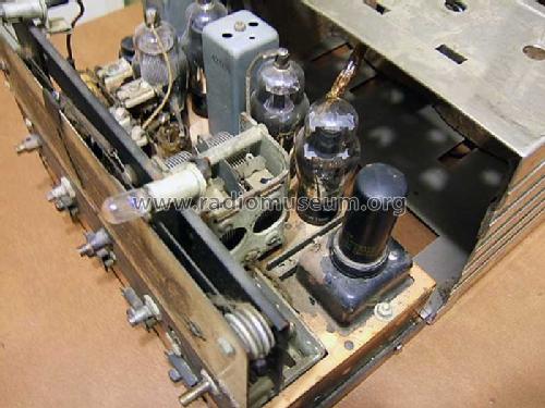
- Number of Tubes
- 6
- Main principle
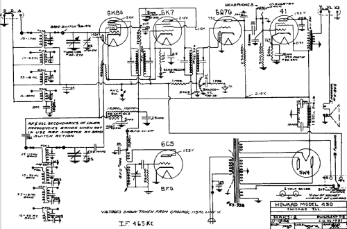
- Superheterodyne (common); ZF/IF 465 kHz; 2 AF stage(s)
- Tuned circuits
- 6 AM circuit(s)
- Wave bands
- Wave Bands given in the notes.
- Power type and voltage
- Alternating Current supply (AC) / 115 Volt
- Loudspeaker
- Electro Magnetic Dynamic LS (moving-coil with field excitation coil)
- Power out
- 1.5 W (unknown quality)
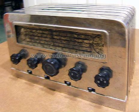
- Material
- Metal case
- from Radiomuseum.org
- Model: 430-2 Series 2 - Howard Radio Company; Chicago,
- Shape
- Tablemodel without push buttons, Mantel/Midget/Compact up to 14
- Dimensions (WHD)
- 11.5 x 7.5 x 6.625 inch / 292 x 191 x 168 mm
- Notes
- The original set model 430 Series 2 is housed in a metal case painted black. Only the bands acress the top and sides are painted silver. General coverage Amateur band receiver. 550 - 1700 kHz, 1700 - 5500 kHz, 5.5 - 18.0 MHz and 16.0 - 40.0 MHz bands. BFO. There are 4 switches below the control knobs: BFO-Off / On; Receive/Send (no transmitter but that the set is not damaged when transmitting with a nearby transmitter); Not sure but it should be on the schematic; Power- Off/On.
- External source of data
- James Cooke, KF5IHM, USA
- Circuit diagram reference
- Rider's Perpetual, Volume 10 = 1939 and before
- Other Models
-
Here you find 354 models, 157 with images and 214 with schematics for wireless sets etc. In French: TSF for Télégraphie sans fil.
All listed radios etc. from Howard Radio Company; Chicago, IL