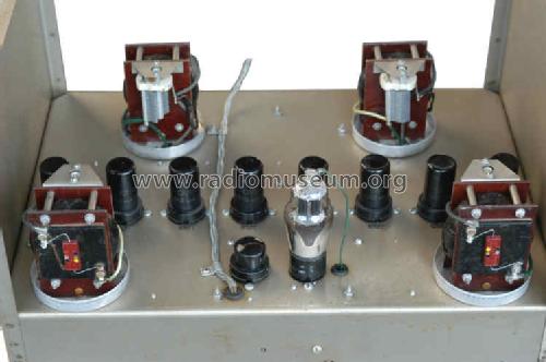
Harmonic Wave Analyzer 300A
Hewlett-Packard, (HP); Palo Alto, CA
- Produttore / Marca
- Hewlett-Packard, (HP); Palo Alto, CA
- Anno
- 1941
- Categoria
- Strumento da laboratorio
- Radiomuseum.org ID
- 82819
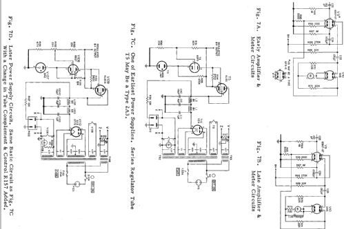
Clicca sulla miniatura dello schema per richiederlo come documento gratuito.
- Numero di tubi
- 21
- Valvole
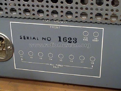
- 6SJ7 6SJ7 6SJ7 6SJ7 6SJ7 6SJ7 6SJ7 6SJ7 6SJ7 6SJ7 6H6 6SN7 6SJ7 6SJ7 6SJ7 6SJ7 6J7 6F6 6SQ7 6L6GA 5U4 0A2
- Principio generale
- Apparecchiatura speciale (descrivere nelle note)
- Gamme d'onda
- Gamme d'onda nelle note.
- Tensioni di funzionamento
- Alimentazione a corrente alternata (CA) / 115 Volt
- Altoparlante
- - - Nessuna uscita audio.
- Materiali
- Mobile di metallo
- Radiomuseum.org
- Modello: Harmonic Wave Analyzer 300A - Hewlett-Packard, HP; Palo Alto
- Forma
- Soprammobile verticale (sviluppato in altezza; no cattedrale, sin decorazioni).
- Annotazioni
-
Info of HPs page:
The 300A measured the individual harmonic present in the output voltage of an amplifier. It consisted of a balanced detector, a local oscillator and a tuned amplifier. Galvin Manufacturing Company, maker of Motorola radio equipment, was an early customer.
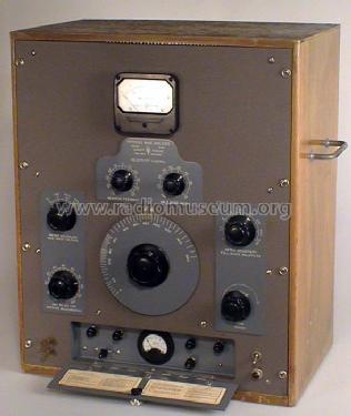
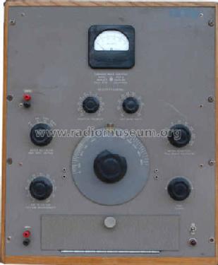
Note the wooden case. In the early 1940s it was customary to have measurement equipment in wooden cabinets. Most cabinets were made of walnut, but Bill Hewlett and Dave Packard decided to use oak. As HP enlarged its line, Bill and Dave gave up using wood because it served no useful purpose and added to the cost.
Test and measurement devices were HP's first products. Its first product was an audio oscillator-a device used to test sound equipment-introduced in 1938 as a prototype by Bill Hewlett. In later years, HP continued as a leader in this category, making instruments for measurement, medical technology and chemical analysis. In 1939 followed the 200A, 200B and in 1941 this Wave Analyzer. Because of the WW2 the next product was only made well after the war.see also -hp- Distortion Measuring Equipment
- Fonte dei dati
- -- Collector info (Sammler)
- Autore
- Modello inviato da Ernst Erb. Utilizzare "Proponi modifica" per inviare ulteriori dati.
- Altri modelli
-
In questo link sono elencati 393 modelli, di cui 361 con immagini e 138 con schemi.
Elenco delle radio e altri apparecchi della Hewlett-Packard, (HP); Palo Alto, CA
Collezioni
Il modello Harmonic Wave Analyzer fa parte delle collezioni dei seguenti membri.
Discussioni nel forum su questo modello: Hewlett-Packard, HP;: Harmonic Wave Analyzer 300A
Argomenti: 1 | Articoli: 1
Harmonic Wave Analyzer
"From HP Catalog 18A" Laboratory Instruments", Copyrighted 1945."

ADVANTAGES:
Direct reading
Simplified operation
Variable selectivity
Wide voltage range
Linear meter scale
USE IT TO ANALYZE:
Noise characteristics
Broadcast amplifier characteristics
Modulating amplifier distortion
Recording devices
Rotating machinery harmonic voltages
Film sound track distortion
Recording distortion Hum
Network characteristics
VARIABLE SELECTIVITY PROVIDES RAPID, ACCURATE WAVE ANALYSIS
This -hp- Model 300A Harmonic Wave Analyzer is a selective voltmeter designed to measure the individual components of complex waves. The selectivity can be varied by means of a unique selective amplifier. Where the harmonics are close together the high selectivity easily separates the wave components. Yet, where the components are spaced far apart, the selectivity may be widened to increase the speed of operation without sacrificing essential accuracy. This feature is also valuable where it is necessary to measure distortion of waves containing a small amount of frequency modulation, such as in sound tracks, and may be used conveniently to integrate a small portion of the audio spectrum in noise measurements and the like. Maximum selectivity is sufficient to separate harmonic components spaced 30 cycles apart. see figure 1.
DIRECT READING
The -hp- Model 300A Harmonic Wave Analyzer covers the audio spectrum from 30 cps to 16,000 cps. The wide voltage range covers the values encountered in nearly every application. Full scale voltmeter readings may be obtained with inputs of .001 to 500 volts so that the instrument may be used with equal success with low output transducers and high power modulating amplifiers. Other features which make it unexcelled for both laboratory and production testing are the linear meter scales fully protected against overloads, and the built-in calibrating system to standardize voltage measurements.
THEORY
The circuit of the Model 300A consists of a variable local oscillator, a balanced modulator, a selective amplifier, and an indicating meter. The variable local oscillator modulates the unknown frequency to produce a constant difference frequency. This difference frequency is applied to the selective amplifier, the output of which is then proportional to the magnitude of the unknown voltage. A meter in the output of the selective amplifier indicates the magnitude of the voltage.
The local oscillator is of the resistance-tuned type, providing a very stable, accurate voltage. A balanced modulator is used to eliminate the local oscillator frequency and to keep cross-modulation products very low. The selective amplifier consists of four tuned circuits in which the effective Q is controlled by positive feedback. Negative feedback is also used to stabilize the amplifier.
This amplifier has the unique characteristic that its selectivity may be varied over a wide range without appreciably affecting the gain of the amplifier.

USES
The Model 300A is well adapted to the measurement of the harmonic distortion in audio frequency equipment of all kinds, broadcast receivers, transmitters; to determine the harmonic components in a-c machinery and power systems; to the study of induced voltages on telephone lines; to measurement of hum components in rectifier circuits.
Other uses include the study of noise by integrating portions of the spectrum with the selectivity control adjusted for a wide pass band and the checking of wave filter characteristics with maximum selectivity.
The -hp- 300A is also useful as a device to measure the amount of cross- or inter-modulation products generated by the simultaneous transmission of two frequencies by an audio system or to measure demodulation of a modulated wave applied through an audio system.
SPECIFICATIONS
Frequency Range: The frequency range is from 30 to 16,000 cps and the frequency calibration is within 3%. The frequency is controlled by a 7" diameter dial located on the panel. The entire range is covered in approximately a 200° sweep of the dial.
Voltage Range: There are four input voltage ranges having maximum values of 0.5 volts, 5 volts, 50 volts, and 500 volts. In addition, a meter multiplier divides each voltage range into full scale meter readings of 500, 250, 100, 50, 25, 10, 5, 2.5, and 1. Thus full scale meter readings can be obtained on from 1 mv to 500 v. Two controls select the input range and meter multiplier. The linear meter is fully protected against overloads.
Selectivity: The selectivity can be varied by means of a control on the front panel. At the maximum selectivity setting, the response is down 3 db at 3 cycles, 10 db at 8 cycles, 40 db at 30 cycles, and 60 db at 53 cycles from maximum response. At minimum selectivity the response is down 3 db at 20 cycles, 10 db at 43 cycles, 40 db at 145 cycles, and 60 db at 280 cycles from maximum response. Selectivity may be varied continuously between these limits. The variable selectivity control is calibrated in the half band width at which the response is down 40 db.
Voltage Accuracy: The over-all voltage accuracy is ±5%, provided adjacent harmonics are within limits determined by the selectivity. This accuracy can be maintained provided that unwanted voltages are attenuated by the selectivity of the instrument to less than 1/3 of the voltage being measured. Thus, with maximum selectivity a 3% second harmonic of a 30 cycle voltage may be measured with 5% accuracy.
The residual modulation products are suppressed by at least 65 db. Hum is at least 75 db below maximum input voltage on any of the four input ranges.
Input Impedance: The input impedance is 200,000 ohms. The input circuit includes a potentiometer which is set to maximum for voltage measurements.
Power Supply: The instrument contains a voltage regulated power supply which operates from 115 volts, 50/60 cycles. Power required is 105 watts.
Mounting: The Model 300A is mounted in an attractive oak cabinet to harmonize with the panel which is finished in wrinkle gray with machine engraved designations. A relay rack model is also available and is designated as the Model 300AR.
Physical: Over-all dimensions of the Model 300A are 24" high, 21 5/8" wide,
and 14 1/8" deep.
Net weight is 78 pounds; shipping weight is 150 pounds.
Pius Steiner, 23.Sep.12


