- Land
- USA
- Hersteller / Marke
- Katzenstein & Keene, New York, NY, USA
- Jahr
- 1934 ?
- Kategorie
- Rundfunkempfänger (Radio - oder Tuner nach WW2)
- Radiomuseum.org ID
- 85801
- Anzahl Röhren
- 5
- Hauptprinzip
- 1 NF-Stufe(n)
- Wellenbereiche
- Langwelle, Mittelwelle (LW+MW).
- Betriebsart / Volt
- Allstromgerät / 110 Volt
- Lautsprecher
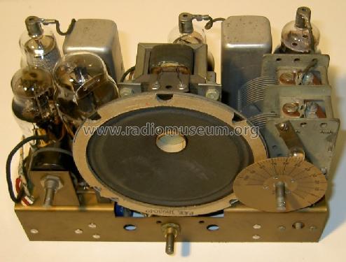
- Dynamischer LS, mit Erregerspule (elektrodynamisch) / Ø 12.7 cm = 5 inch
- Belastbarkeit / Leistung
- 1 W (Qualität unbekannt)
- Material
- Gerät mit Holzgehäuse
- von Radiomuseum.org
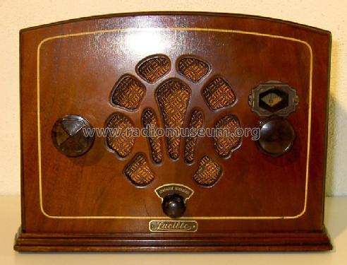
- Modell: Lucille - Katzenstein & Keene, New York
- Form
- Tischgerät ohne Drucktasten, bis 35 cm Breite (Kleingerät, meist dekorativ. Nur für Netzbetrieb, doch Transportgriff möglich).
- Abmessungen (BHT)
- 270 x 190 x 140 mm / 10.6 x 7.5 x 5.5 inch
- Bemerkung
- Resistance cord.
- Datenherkunft
- - - Data from my own collection
- Autor
- Modellseite von Christian ADAM angelegt. Siehe bei "Änderungsvorschlag" für weitere Mitarbeit.
- Weitere Modelle
-
Hier finden Sie 1 Modelle, davon 1 mit Bildern und 0 mit Schaltbildern.
Alle gelisteten Radios usw. von Katzenstein & Keene, New York, NY, USA
Sammlungen
Das Modell Lucille befindet sich in den Sammlungen folgender Mitglieder.
Forumsbeiträge zum Modell: Katzenstein & Keene,: Lucille
Threads: 1 | Posts: 9
Hi Rmorg, who can dive in and help?
I own this very nice midget radio, Model LUCILLE, from KATZENSTEIN & KEENE, New York, USA
http://www.radiomuseum.org/r/katzen_lucille.html
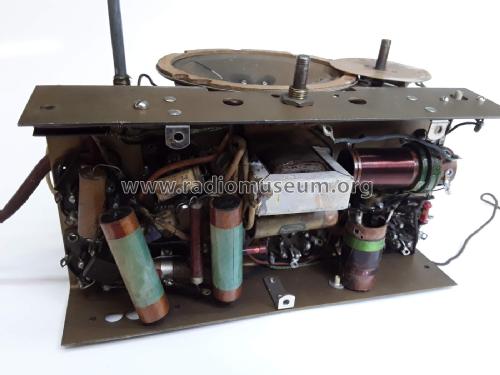
Today I could repair it, but have replaced the missing power cord with integrated resistor by a 125 Ohms resistor, according to my calculation, for a main voltage of 110V. So my first question: is it still possible to buy a replacement power cord, like the original? If not, who has a solution? On my side, I have integrated the replacement resistor on the chassis. Without the cabinet, every thing is OK, but I am effraid about the additional heat generation when the wood cabinet will be mounted (risk of damage)...
And by the way, does somebody know more about this make? I could find nothing with Google. Has somebody the schematic? The first filtering capacitor was 32µF, the second 16µF, is this OK? (those in place were not the original).
Thanks a lot for sharing info and tricks,
Christian ADAM
Christian ADAM, 25.Mar.07


